Nissan Frontier. Manual - part 726


  Index      Nissan     Nissan Frontier (2014 year) - Service and Repair Manual


Search            


Content   ..  724  725  726  727   ..


Nissan Frontier. Manual - part 726


ENGINE UNIT

EM-93

< UNIT DISASSEMBLY AND ASSEMBLY >

[QR25DE]

C

D

E

F

G

H

I

J

K

L

M

A

EM

N

P

O

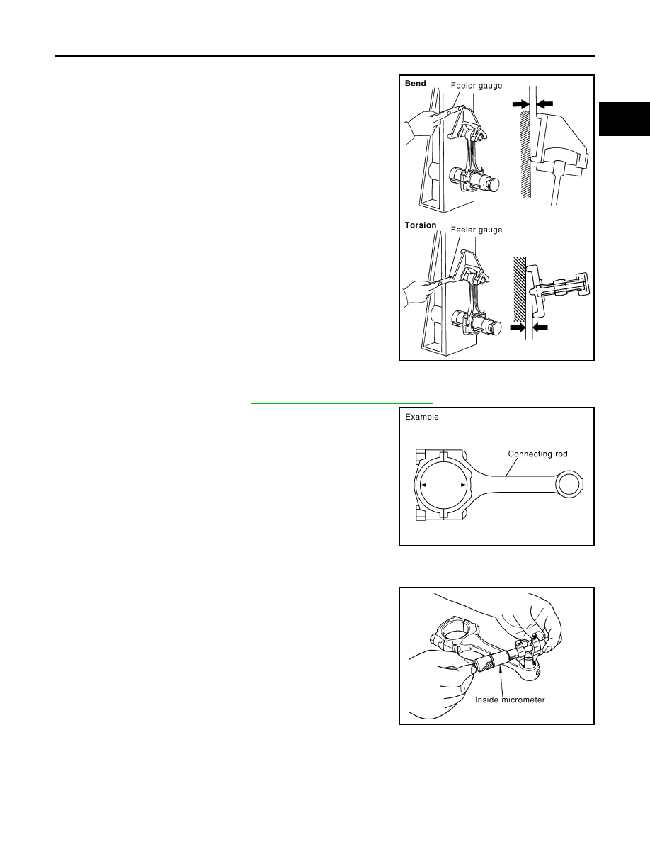
CONNECTING ROD BEND AND TORSION

• Check with a connecting rod aligner.

• If it exceeds the limit, replace connecting rod assembly.

CONNECTING ROD BIG END DIAMETER

• Install connecting rod bearing cap without connecting rod bearing installed, and tightening connecting rod

bolts to the specified torque. Refer to 

EM-81, "Disassembly and Assembly"

 for the tightening procedure.

• Measure the inner diameter of connecting rod big end with an

inside micrometer.

• If out of the standard, replace connecting rod assembly.

CONNECTING ROD BUSHING OIL CLEARANCE

Connecting Rod Bushing Inner Diameter

Measure the inner diameter of connecting rod bushing with an inside

micrometer.

Piston Pin Outer Diameter

Bend: 

Limit: 0.15 mm (0.0059 in) per 100 mm (3.94 in) length

Torsion:

Limit: 0.30 mm (0.0118 in) per 100 mm (3.94 in) length

PBIC2077E

Standard: 48.000 - 48.013 mm (1.8898 - 1.8903 in)

PBIC1641E

Standard: 20.000 - 20.012 mm (0.7874 - 0.7879 in)

PBIC0120E

EM-94

< UNIT DISASSEMBLY AND ASSEMBLY >

[QR25DE]

ENGINE UNIT

Measure the outer diameter of piston pin with a micrometer.

Connecting Rod Bushing Oil Clearance

(Connecting rod bushing oil clearance) = (Connecting rod bushing inner diameter) – (Piston pin outer diame-

ter)

• If the measured value is out of the standard, replace connecting rod assembly and/or piston and piston pin

assembly.

• If replacing piston and piston pin assembly. Refer to 

EM-108, "Standard and Limit"

.

• If replacing connecting rod assembly. Refer to 

EM-108, "Standard

and Limit"

 to select connecting rod bearing.

Factory installed parts grading:

• Service parts apply only to grade “0”.

Unit: mm (in)

*: After installing in connecting rod. 

CYLINDER BLOCK DISTORTION

• Remove gasket on the cylinder block surface, and also remove engine oil, scale, carbon, or other contami-

nation; using suitable tool. 

CAUTION:

Do not allow any debris to enter engine oil or engine coolant passages.

Standard: 19.989 - 20.001 mm (0.7870 - 0.7874 in)

PBIC0117E

Standard: 0.005 - 0.017 mm (0.0002 - 0.0007 in)

PBIC2196E

               Grade

                    0

                    1

Connecting rod bushing 
inner diameter

*

         20.000 - 20.006          
       (0.7874 - 0.7876)

         20.006 - 20.012
        (0.7876 - 0.7879)

Piston pin hole diameter

19.993 - 19.999

(0.7871 - 0.7874)

         19.999 - 20. 005
        (0.7874 - 0.7876)

Piston pin outer diameter

        19.989 - 19.995
       (0.7870 - 0.7872)

         19.995 - 20.001
        (0.7872 - 0.7874)

PBIC3019E

ENGINE UNIT

EM-95

< UNIT DISASSEMBLY AND ASSEMBLY >

[QR25DE]

C

D

E

F

G

H

I

J

K

L

M

A

EM

N

P

O

• Measure the distortion on the cylinder block upper face at some

different points in six directions with straightedge and feeler gauge.

• If it exceeds the limit, replace cylinder block and lower cylinder

block assembly.

NOTE:

Cylinder block cannot be replaced as a single part, because it is

machined together with lower cylinder block.

MAIN BEARING HOUSING INNER DIAMETER

• Install lower cylinder block without main bearings installed, and

tighten lower cylinder block bolts to the specified torque. Refer to

EM-81, "Disassembly and Assembly"

 for the tightening procedure.

• Measure the inner diameter of main bearing housing with a bore

gauge. 

• If out of the standard, replace cylinder block and lower cylinder

block assembly. 

NOTE:

Cylinder block cannot be replaced as a single part, because it is

machined together with lower cylinder block.

PISTON TO CYLINDER BORE CLEARANCE

Cylinder Bore Inner Diameter

• Using a bore gauge, measure the cylinder bore for wear, out-of-

round and taper at six different points on each cylinder. [(X) and (Y)

directions at (A), (B) and (C)] [(Y) is in longitudinal direction of the

engine].

NOTE:

When determining cylinder bore grade, measure cylinder bore at

(B) position.

• If the measured value exceeds the limit, or if there are scratches and/or seizure on the cylinder inner wall,

hone or re-bore the cylinder inner wall. 

Piston Skirt Diameter

Limit: 0.1 mm (0.004 in)

PBIC0121E

Standard: 58.944 - 58.968 mm (2.3206 - 2.3216 in)

PBIC2012E

Standard inner diameter:

89.010 - 89.030 mm (3.5043 - 3.5051 in)

Wear limit:

0.2 mm (0.008 in)

Out-of-round [Difference between (X) and (Y)]:

0.015 mm (0.0006 in)

Taper limit [Difference between (A) and (C)]:

0.01 mm (0.0004 in)

SBIA0284E

EM-96

< UNIT DISASSEMBLY AND ASSEMBLY >

[QR25DE]

ENGINE UNIT

Measure the outer diameter of piston skirt with a micrometer.

Piston to Cylinder Bore Clearance

Calculate by piston skirt diameter and cylinder bore inner diameter [direction (X), position (B)].

(Clearance) = (Cylinder bore inner diameter) – (Piston skirt diameter)

• If it exceeds the limit, replace piston and piston pin assembly. Refer to 

EM-101, "How to Select Piston and

Bearing"

.

Re-boring Cylinder Bore

1. Cylinder bore size is determined by adding piston to cylinder bore clearance to piston skirt diameter.

2. Install lower cylinder block, and tighten bolts to the specified torque. Otherwise, cylinder bores may be dis-

torted in final assembly. Refer to 

EM-81, "Disassembly and Assembly"

 for the tightening procedure.

3. Cut cylinder bores.

NOTE:

• When any cylinder needs boring, all other cylinders must also be bored.

• Do not cut too much out of cylinder bore at a time. Cut only 0.05 mm (0.0020 in) or so in diameter at a

time.

4. Hone cylinders to obtain the specified piston to cylinder bore clearance.
5. Measure the finished cylinder bore for out-of-round and taper.

NOTE:

Measurement should be done after cylinder bore cools down.

CRANKSHAFT MAIN JOURNAL DIAMETER

• Measure the outer diameter of crankshaft main journals with a

micrometer.

• If out of the standard, measure the main bearing oil clearance.

Then use undersize bearing. Refer to 

EM-108, "Standard and

Limit"

.

CRANKSHAFT PIN JOURNAL DIAMETER 

Measure point

: Distance from the top 42.98 mm (1.692 in)

Standard

: 88.990 - 89.010 mm (3.5035 - 3.5043 in)

PBIC0125E

Standard

: 0.010 - 0.030 mm (0.0004 - 0.0012 in)

Limit

: 0.08 mm (0.0031 in)

Re-bored size calculation: D = A + B - C
where,
D: Bored diameter
A: Piston diameter as measured
B: Piston - to - cylinder bore clearance (standard value)
C: Honing allowance 0.02 mm (0.0008 in)

Standard: 54.955 - 54.979 mm (2.1636 - 2.1645 in) dia.

PBIC0270E


Content   ..  724  725  726  727   ..