Nissan Frontier. Manual - part 708
CAMSHAFT VALVE CLEARANCE
EM-21
< PERIODIC MAINTENANCE >
[QR25DE]
C
D
E
F
G
H
I
J
K
L
M
A
EM
N
P
O
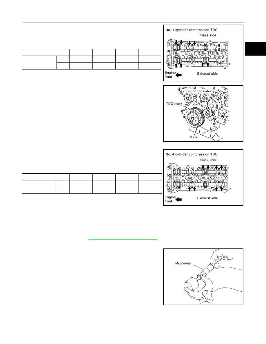
• Measure the valve clearances at locations marked “
×” as
shown in the table below (locations indicated with black arrow
shown) with feeler gauge.
• No. 1 cylinder compression TDC
c. Rotate crankshaft one revolution (360
°) and align TDC mark to
timing indicator on front cover.
• Measure the valve clearance at locations marked “
×” as shown
in the table below (locations indicated with black arrow shown)
with feeler gauge.
• No. 4 cylinder compression TDC
5. If out of standard, perform adjustment.
ADJUSTMENT
• Perform adjustment depending on selected head thickness of valve lifter.
1. Measure the valve clearance.
2. Remove camshaft. Refer to
EM-54, "Removal and Installation"
3. Remove valve lifters at the locations that are out of the standard.
4. Measure the center thickness of the removed valve lifters with a
micrometer.
5. Use the equation below to calculate valve lifter thickness for replacement.
Measuring position
No. 1 CYL.
No. 2 CYL.
No. 3 CYL.
No. 4 CYL.
No. 1 cylinder at
compression TDC
INT
×
×
EXH
×
×
PBIC3017E
PBIC3015E
Measuring position
No. 1 CYL.
No. 2 CYL.
No. 3 CYL.
No. 4 CYL.
No. 4 cylinder at
compression TDC
INT
×
×
EXH
×
×
PBIC3026E
KBIA0057E