Nissan Frontier. Manual - part 667


  Index      Nissan     Nissan Frontier (2014 year) - Service and Repair Manual


Search            


Content   ..  665  666  667  668   ..


Nissan Frontier. Manual - part 667


P0456 EVAP CONTROL SYSTEM

EC-1239

< DTC/CIRCUIT DIAGNOSIS >

[VQ40DE FOR MEXICO]

C

D

E

F

G

H

I

J

K

L

M

A

EC

N

P

O

NG

>> Replace fuel level sensor unit. Refer to 

FL-10, "Removal and Installation"

.

24.

CHECK INTERMITTENT INCIDENT

Refer to 

GI-42, "Intermittent Incident"

.

>> INSPECTION END

Component Inspection

INFOID:0000000009481877

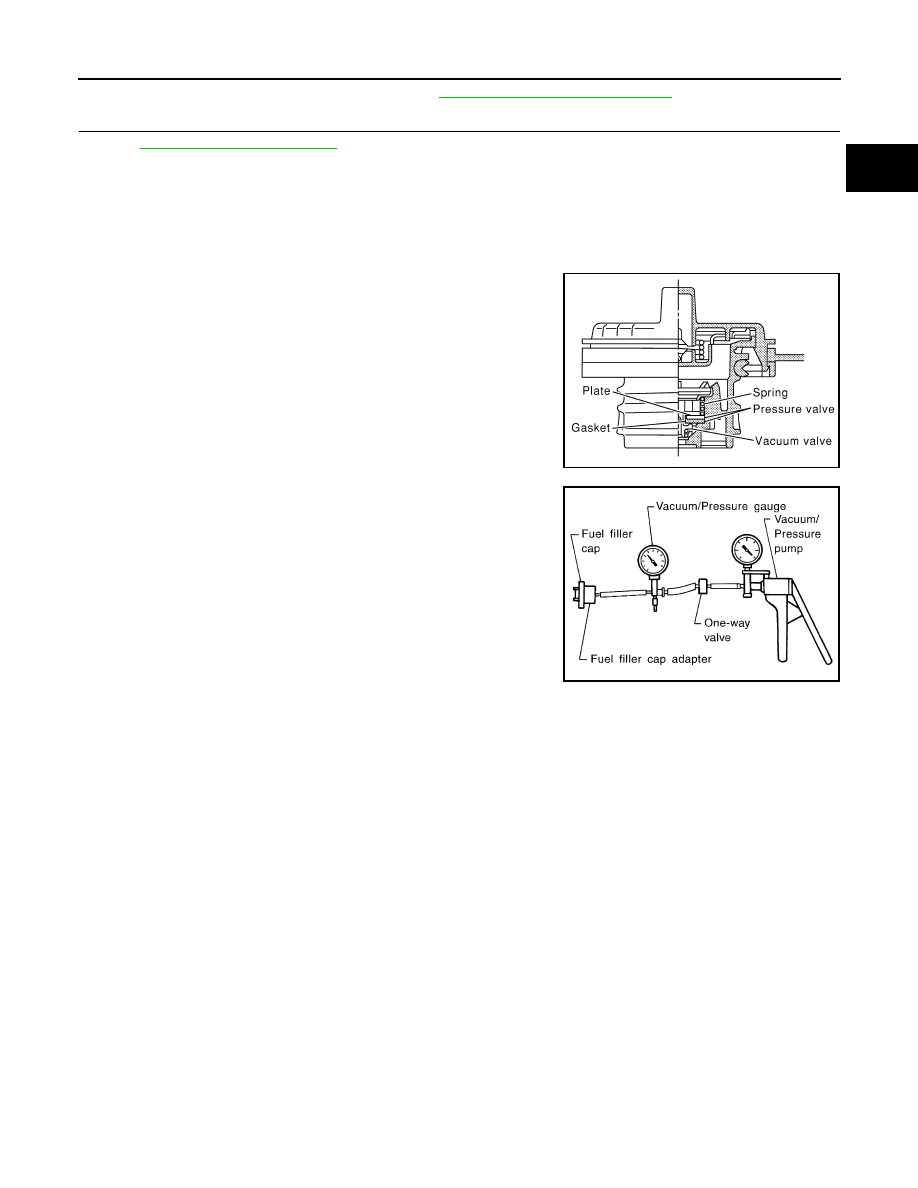
FUEL TANK VACUUM RELIEF VALVE (BUILT INTO FUEL FILLER CAP)

1. Wipe clean valve housing.

2. Check valve opening pressure and vacuum.

3. If out of specification, replace fuel filler cap as an assembly.

CAUTION:

Use only a genuine fuel filler cap as a replacement. If an incor-

rect fuel filler cap is used, the MIL may come on.

SEF445Y

Pressure: 15.3 - 20.0 kPa (0.156 - 0.204 kg/cm

2

, 2.22 - 

2.90 psi)

Vacuum:

6.0 to 3.3 kPa (0.061 to 0.034 kg/cm

2

0.87 to 0.48 psi)

SEF943S

EC-1240

< DTC/CIRCUIT DIAGNOSIS >

[VQ40DE FOR MEXICO]

P0500 VSS

P0500 VSS

Description

INFOID:0000000009481878

NOTE:

• If DTC P0500 is displayed with DTC UXXXX, first perform the trouble diagnosis for DTC UXXXX. 

• If DTC P0500 is displayed with DTC P0607, first perform the trouble diagnosis for DTC P0607. Refer

to 

EC-1253, "DTC Logic"

The vehicle speed signal is sent to the combination meter from the “ABS actuator and electric unit (control

unit)” by CAN communication line. The combination meter then sends a signal to the ECM by CAN communi-

cation line.

On Board Diagnosis Logic

INFOID:0000000009481879

FAIL-SAFE MODE

When the malfunction is detected, ECM enters fail-safe mode.

DTC Confirmation Procedure

INFOID:0000000009481880

CAUTION:

Always drive vehicle at a safe speed.

NOTE:

If DTC Confirmation Procedure has been previously conducted, always perform the following before conduct-

ing the next step.

1. Turn ignition switch OFF and wait at least 10 seconds.

2. Turn ignition switch ON.

3. Turn ignition switch OFF and wait at least 10 seconds.

TESTING CONDITION:

Steps 1 and 2 may be conducted with the drive wheels lifted in the shop or by driving the vehicle. If a

road test is expected to be easier, it is unnecessary to lift the vehicle.

 WITH CONSULT

1. Start engine (VDC switch OFF).

2. Read “VHCL SPEED SE” in “DATA MONITOR” mode with CONSULT. The vehicle speed on CONSULT

should exceed 10 km/h (6 MPH) when rotating wheels with suitable gear position.

If NG, go to 

EC-1241, "Diagnosis Procedure"

.

If OK, go to following step.

3. Select “DATA MONITOR” mode with CONSULT.

4. Warm engine up to normal operating temperature.

5. Maintain the following conditions for at least 60 consecutive seconds.

DTC No.

Trouble diagnosis name

DTC detecting condition

Possible cause

P0500
0500

Vehicle speed sensor

The almost 0 km/h (0 MPH) signal from 
vehicle speed sensor is sent to ECM even 
when vehicle is being driven.

• Harness or connectors

(The CAN communication line is open or short-
ed)

• Harness or connectors

(The vehicle speed signal circuit is open or 
shorted)

• Wheel sensor
• Combination meter
• ABS actuator and electric unit (control unit) 

Detected item

Engine operating condition in fail-safe mode

Vehicle speed sensor

When the fail-safe system for vehicle speed sensor is activated, the cooling fan operates 
(High) while engine is running.

ENG SPEED

1,700 - 6,000 rpm

COOLAN TEMP/S

More than 70

°C (158°F)

B/FUEL SCHDL

6.3 - 31.8 msec

P0500 VSS

EC-1241

< DTC/CIRCUIT DIAGNOSIS >

[VQ40DE FOR MEXICO]

C

D

E

F

G

H

I

J

K

L

M

A

EC

N

P

O

6. Check 1st trip DTC.

7. If 1st trip DTC is detected, go to 

EC-1241, "Diagnosis Procedure"

.

Overall Function Check

INFOID:0000000009481881

Use this procedure to check the overall function of the vehicle speed sensor circuit. During this check, a 1st

trip DTC might not be confirmed.

 WITH GST

1. Lift up drive wheels.

2. Start engine.

3. Read vehicle speed sensor signal in Service $01 with GST.

The vehicle speed sensor on GST should be able to exceed 10 km/h (6 MPH) when rotating wheels with

suitable gear position.

4. If NG, go to 

EC-1241, "Diagnosis Procedure"

.

Diagnosis Procedure

INFOID:0000000009481882

1.

CHECK DTC WITH “ABS ACTUATOR AND ELECTRIC UNIT (CONTROL UNIT)”

Refer to 

BRC-8, "Work Flow"

 (TYPE 1) or 

BRC-120, "Work Flow"

 (TYPE 2).

OK or NG

OK

>> GO TO 2.

NG

>> Repair or replace.

2.

CHECK COMBINATION METER FUNCTION

Refer to 

GI-42, "Intermittent Incident"

.

>> INSPECTION END

Selector lever

Except P or N position

PW/ST SIGNAL

OFF

EC-1242

< DTC/CIRCUIT DIAGNOSIS >

[VQ40DE FOR MEXICO]

P0506 ISC SYSTEM

P0506 ISC SYSTEM

Description

INFOID:0000000009481883

NOTE:

If DTC P0506 is displayed with other DTC, first perform the trouble diagnosis for the other DTC.

The ECM controls the engine idle speed to a specified level through the fine adjustment of the air, which is let

into the intake manifold, by operating the electric throttle control actuator. The operating of the throttle valve is

varied to allow for optimum control of the engine idling speed. The crankshaft position sensor (POS) detects

the actual engine speed and sends a signal to the ECM.

The ECM controls the electric throttle control actuator so that the engine speed coincides with the target value

memorized in the ECM. The target engine speed is the lowest speed at which the engine can operate steadily.

The optimum value stored in the ECM is determined by taking into consideration various engine conditions,

such as during warming up, deceleration and engine load (air conditioner, power steering and cooling fan

operation, etc.). 

On Board Diagnosis Logic

INFOID:0000000009481884

DTC Confirmation Procedure

INFOID:0000000009481885

NOTE:

• If the target idle speed is out of the specified value, perform, 

EC-1075, "Idle Air Volume Learning"

,

before conducting DTC Confirmation Procedure. For the target idle speed, refer to the 

EC-1381

.

• If DTC Confirmation Procedure has been previously conducted, always perform the following before con-

ducting the next step.

1. Turn ignition switch OFF and wait at least 10 seconds.

2. Turn ignition switch ON.

3. Turn ignition switch OFF and wait at least 10 seconds.

TESTING CONDITION:

• Before performing the following procedure,confirm that battery voltage is more than 11V at idle.

• Always perform the test at a temperature above 

10°C(14°F).

1. Start engine and warm it up to normal operating temperature.

2. Turn ignition switch OFF and wait at least 10 seconds.

3. Turn ignition switch ON.

4. Turn ignition switch OFF and wait at least 10 seconds.

5. Start engine and run it for at least 1 minute at idle speed.

6. Check 1st trip DTC.

7. If 1st trip DTC is detected, go to 

EC-1242, "Diagnosis Procedure"

.

Diagnosis Procedure

INFOID:0000000009481886

1.

CHECK INTAKE AIR LEAK

1. Start engine and let it idle.

2. Listen for an intake air leak after the mass air flow sensor.
OK or NG

OK

>> GO TO 2.

NG

>> Discover air leak location and repair.

2.

REPLACE ECM

1. Stop engine.

2. Replace ECM.

3. Perform initialization of NVIS (NATS) system and registration of all NVIS (NATS) ignition key IDs. Refer to

SEC-7, "ADDITIONAL SERVICE WHEN REPLACING CONTROL UNIT : Special Repair Requirement"

.

4. Perform 

EC-1074, "VIN Registration"

.

DTC No.

Trouble diagnosis name

DTC detecting condition

Possible cause

P0506
0506

Idle speed control sys-
tem RPM lower than ex-
pected

The idle speed is less than the target idle speed 
by 100 rpm or more.

• Electric throttle control actuator
• Intake air leak


Content   ..  665  666  667  668   ..