Nissan Frontier. Manual - part 656
P0327, P0328, P0332, P0333 KS
EC-1195
< DTC/CIRCUIT DIAGNOSIS >
[VQ40DE FOR MEXICO]
C
D
E
F
G
H
I
J
K
L
M
A
EC
N
P
O
7.
DETECT MALFUNCTIONING PART
Check the following.
• Harness connectors F67, F250
• Harness connectors F14, E5
• Harness for open or short between knock sensor and ground
>> Repair open circuit or short power in harness or connectors.
8.
CHECK INTERMITTENT INCIDENT
GI-42, "Intermittent Incident"
.
>> INSPECTION END
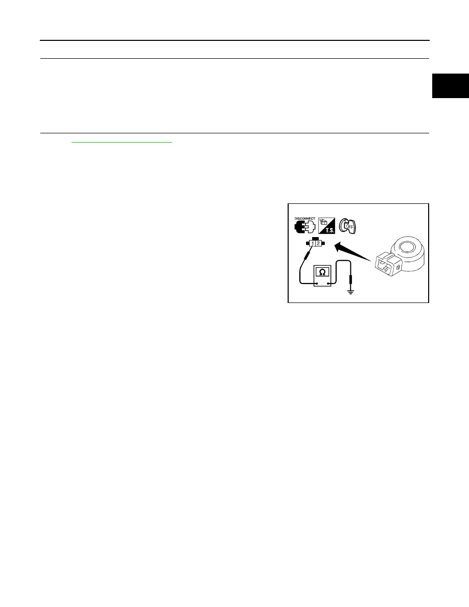
Component Inspection
INFOID:0000000009481839
KNOCK SENSOR
Check resistance between knock sensor terminal 1 and ground.
NOTE:
It is necessary to use an ohmmeter which can measure more
than 10 M
Ω.
CAUTION:
Never use any knock sensors that have been dropped or physi-
cally damaged. Use only new ones.
Resistance: Approximately 532 - 588 k
Ω [at 20°C (68°F)]
SEF227W