Nissan Frontier. Manual - part 634
P0075, P0081 IVT CONTROL SOLENOID VALVE
EC-1107
< DTC/CIRCUIT DIAGNOSIS >
[VQ40DE FOR MEXICO]
C
D
E
F
G
H
I
J
K
L
M
A
EC
N
P
O
P0075, P0081 IVT CONTROL SOLENOID VALVE
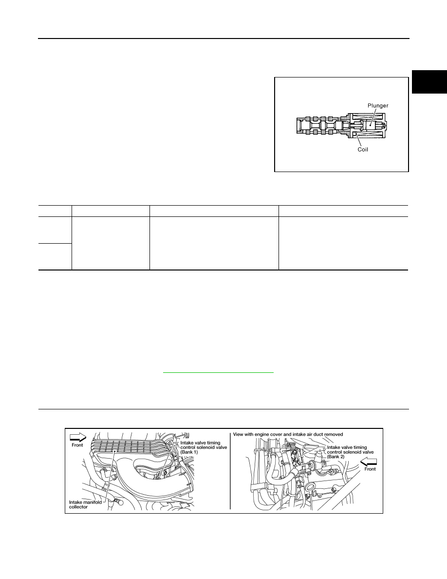
Component Description
INFOID:0000000009481751
Intake valve timing control solenoid valve is activated by ON/OFF
pulse duty (ratio) signals from the ECM.
The intake valve timing control solenoid valve changes the oil
amount and direction of flow through intake valve timing control unit
or stops oil flow.
The longer pulse width advances valve angle.
The shorter pulse width retards valve angle.
When ON and OFF pulse widths become equal, the solenoid valve
stops oil pressure flow to fix the intake valve angle at the control
position.
On Board Diagnosis Logic
INFOID:0000000009481752
DTC Confirmation Procedure
INFOID:0000000009481753
1. If DTC Confirmation Procedure has been previously conducted, always perform the following before con-
ducting the next step.
a. Turn ignition switch OFF and wait at least 10 seconds.
b. Turn ignition switch ON.
c. Turn ignition switch OFF and wait at least 10 seconds.
2. Start engine and let it idle for 5 seconds.
3. Check 1st trip DTC.
4. If 1st trip DTC is detected, go to
EC-1107, "Diagnosis Procedure"
Diagnosis Procedure
INFOID:0000000009481754
1.
CHECK INTAKE VALVE TIMING CONTROL SOLENOID VALVE POWER SUPPLY CIRCUIT
1. Turn ignition switch OFF.
2. Disconnect intake valve timing control solenoid valve harness connector.
3. Turn ignition switch ON.
PBIB1842E
DTC No.
Trouble diagnosis name
DTC detecting condition
Possible cause
P0075
0075
(Bank 1)
Intake valve timing control
solenoid valve circuit
An improper voltage is sent to the ECM
through intake valve timing control solenoid
valve.
• Harness or connectors
(Intake valve timing control solenoid valve
circuit is open or shorted.)
• Intake valve timing control solenoid valve
P0081
0081
(Bank 2)
BBIA0553E