Nissan Frontier. Manual - part 614
ECM
EC-1027
< ECU DIAGNOSIS INFORMATION >
[VQ40DE FOR MEXICO]
C
D
E
F
G
H
I
J
K
L
M
A
EC
N
P
O
73
Y
Engine coolant temperature
sensor
[Engine is running]
Approximately 0 - 4.8V
Output voltage varies with engine
coolant temperature.
74
W
Heated oxygen sensor 2
(Bank 1)
[Engine is running]
• Revving engine from idle to 3,000 rpm
quickly after the following conditions are
met
- Engine: After warming up
- Keeping the engine speed between 3,500
and 4,000 rpm for 1 minute and at idle for 1
minute under no load
0 - Approximately 1.0V
75
B/R
A/F sensor 1 (Bank 2)
[Ignition switch: ON]
Approximately 1.8V
78
GR
Sensor ground
(Heated oxygen sensor 2)
[Engine is running]
• Warm-up condition
• Idle speed
Approximately 0V
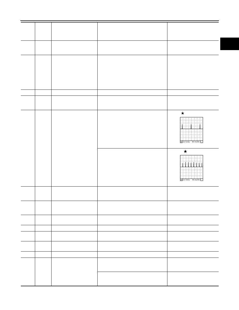
79
80
81
P
GR
G
Ignition signal No. 6
Ignition signal No. 4
Ignition signal No. 2
[Engine is running]
• Warm-up condition
• Idle speed
NOTE:
The pulse cycle changes depending on rpm
at idle
0 - 0.2V
[Engine is running]
• Warm-up condition
• Engine speed: 2,500 rpm
0.1 - 0.4V
82
B
Sensor ground
(APP sensor 1)
[Engine is running]
• Warm-up condition
• Idle speed
Approximately 0V
83
BG
Sensor ground
(APP sensor 2)
[Engine is running]
• Warm-up condition
• Idle speed
Approximately 0V
85
W
Data link connector
[Ignition switch: ON]
• CONSULT or GST: disconnected
Approximately 5V - Battery volt-
age (11 - 14V)
86
P
CAN communication line
—
—
90
L
Sensor power supply
(APP sensor 1)
[Ignition switch: ON]
Approximately 5V
91
G
Sensor power supply
(APP sensor 2)
[Ignition switch: ON]
Approximately 5V
94
L
CAN communication line
—
—
98
GR
Accelerator pedal position
sensor 2
[Ignition switch: ON]
• Engine: Stopped
• Accelerator pedal: Fully released
0.28 - 0.48V
[Ignition switch: ON]
• Engine: Stopped
• Accelerator pedal: Fully depressed
More than 2.0
TER-
MI-
NAL
NO.
WIRE
COLOR
ITEM
CONDITION
DATA (DC Voltage)
SEC986C
SEC987C