Nissan Frontier. Manual - part 570
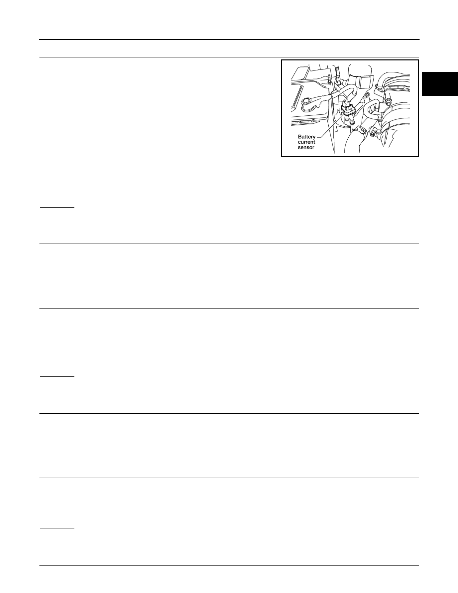
P1551, P1552 BATTERY CURRENT SENSOR
EC-851
< DTC/CIRCUIT DIAGNOSIS >
[VQ40DE FOR USA AND CANADA]
C
D
E
F
G
H
I
J
K
L
M
A
EC
N
P
O
2.
CHECK BATTERY CURRENT SENSOR POWER SUPPLY CIRCUIT
1. Disconnect battery current sensor harness connector.
2. Turn ignition switch ON.
3. Check voltage between battery current sensor terminal 1 and ground with CONSULT or tester.
OK or NG
OK
>> GO TO 4.
NG
>> GO TO 3.
3.
DETECT MALFUNCTIONING PART
Check the following.
• Harness connectors E5, F14
• Harness for open or short between battery current sensor and ECM
>> Repair circuit or short to ground or short to power in harness or connectors.
4.
CHECK BATTERY CURRENT SENSOR GROUND CIRCUIT FOR OPEN AND SHORT
1. Turn ignition switch OFF.
2. Disconnect ECM harness connector.
3. Check harness continuity between battery current sensor terminal 2 and ECM terminal 68.
4. Also check harness for short to ground and short to power.
OK or NG
OK
>> GO TO 6.
NG
>> GO TO 5.
5.
DETECT MALFUNCTIONING PART
Check the following.
• Harness connectors E5, F14
• Harness for open or short between battery current sensor and ECM
>> Repair circuit or short to ground or short to power in harness or connectors.
6.
CHECK BATTERY CURRENT SENSOR INPUT SIGNAL CIRCUIT FOR OPEN AND SHORT
1. Check harness continuity between battery current sensor terminal 3 and ECM terminal 66.
2. Also check harness for short to ground and short to power.
OK or NG
OK
>> GO TO 8.
NG
>> GO TO 7.
7.
DETECT MALFUNCTIONING PART
BBIA0582E
Voltage: Approximately 5V
Continuity should exist.
Continuity should exist.