Nissan Frontier. Manual - part 534


  Index      Nissan     Nissan Frontier (2014 year) - Service and Repair Manual


Search            


Content   ..  532  533  534  535   ..


Nissan Frontier. Manual - part 534


P0172, P0175 FUEL INJECTION SYSTEM FUNCTION

EC-707

< DTC/CIRCUIT DIAGNOSIS >

[VQ40DE FOR USA AND CANADA]

C

D

E

F

G

H

I

J

K

L

M

A

EC

N

P

O

7. If it is difficult to start engine at step 6, the fuel injection system has a malfunction, too.
8. Crank engine while depressing accelerator pedal.

If engine starts, go to 

EC-707, "Diagnosis Procedure"

. If engine does not start, remove spark plugs and

check for fouling, etc.

 WITH GST

1. Start engine and warm it up to normal operating temperature.
2. Turn ignition switch OFF and wait at least 10 seconds.
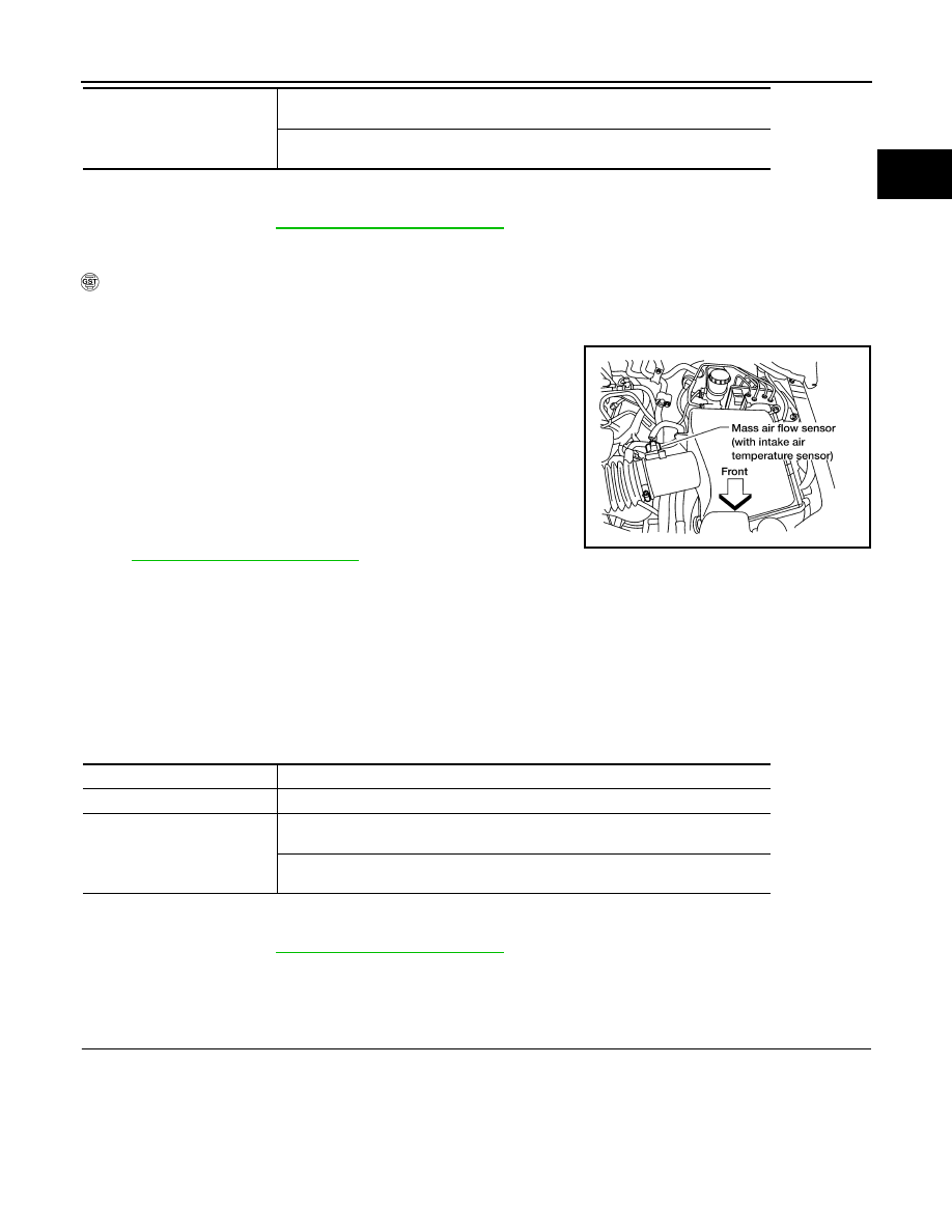
3. Disconnect mass air flow sensor harness connector. Then

restart and run engine for at least 5 seconds at idle speed.

4. Stop engine and reconnect mass air flow sensor harness con-

nector.

5. Select Service $03 with GST. Make sure DTC P0102 is

detected.

6. Select Service $04 with GST and erase the DTC P0102.
7. Start engine again and let it idle for at least 10 minutes.
8. Select Service $07 with GST. The 1st trip DTC P0172 or P0175

should be detected at this stage, if a malfunction exists. If so, go

to 

EC-707, "Diagnosis Procedure"

.

NOTE:

If 1st trip DTC is not detected during above procedure, performing the following procedure is advised.

a. Turn ignition switch OFF and wait at least 10 seconds.
b. Start engine and drive the vehicle under the similar conditions to (1st trip) Freeze Frame Data for 10 min-

utes. Refer to the table below.

Hold the accelerator pedal as steady as possible.

The similar conditions to (1st trip) Freeze Frame Data means the vehicle operation that the following con-

ditions should be satisfied at the same time.

9. If it is difficult to start engine at step 7, the fuel injection system has a malfunction.
10. Crank engine while depressing accelerator pedal.

If engine starts, go to 

EC-707, "Diagnosis Procedure"

. If engine does not start, remove spark plugs and

check for fouling, etc.

Diagnosis Procedure

INFOID:0000000009481362

1.

CHECK EXHAUST GAS LEAK

1. Start engine and run it at idle.

Engine coolant temperature (T) 
condition

When the freeze frame data shows lower than 70 

°C (158 °F),

T should be lower than 70 

°C (158 °F).

When the freeze frame data shows higher than or equal to 70 

°C (158 °F),

T should be higher than or equal to 70 

°C (158 °F).

BBIA0368E

Engine speed

Engine speed in the freeze frame data 

± 400 rpm

Vehicle speed

Vehicle speed in the freeze frame data 

± 10 km/h (6 MPH)

Engine coolant temperature (T) 
condition

When the freeze frame data shows lower than 70 

°C (158 °F),

T should be lower than 70 

°C (158 °F).

When the freeze frame data shows higher than or equal to 70 

°C (158 °F),

T should be higher than or equal to 70 

°C (158 °F).

EC-708

< DTC/CIRCUIT DIAGNOSIS >

[VQ40DE FOR USA AND CANADA]

P0172, P0175 FUEL INJECTION SYSTEM FUNCTION

2. Listen for an exhaust gas leak before three way catalyst (manifold).

OK or NG

OK

>> GO TO 2.

NG

>> Repair or replace.

2.

CHECK FOR INTAKE AIR LEAK

Listen for an intake air leak after the mass air flow sensor.
OK or NG

OK

>> GO TO 3.

NG

>>  Repair or replace.

3.

CHECK A/F SENSOR 1 INPUT SIGNAL CIRCUIT

1. Turn ignition switch OFF.

2. Disconnect corresponding A/F sensor 1 harness connector.

3. Disconnect ECM harness connector.

4. Check harness continuity between A/F sensor 1 terminal and ECM terminal as follows.

Refer to Wiring Diagram.

5. Check harness continuity between the following terminals and ground.

Refer to Wiring Diagram.

6. Also check harness for short to power.

PBIB1216E

Bank 1

A/F sensor 1 terminal

ECM terminal

1

69

2

73

Bank 2

1

77

2

81

Continuity should exist.

Bank 1

Bank 2

A/F sensor 1 terminal

ECM terminal

A/F sensor 1 terminal

ECM terminal

1

69

1

77

2

73

2

81

Continuity should not exist.

BBIA0544E

P0172, P0175 FUEL INJECTION SYSTEM FUNCTION

EC-709

< DTC/CIRCUIT DIAGNOSIS >

[VQ40DE FOR USA AND CANADA]

C

D

E

F

G

H

I

J

K

L

M

A

EC

N

P

O

OK or NG

OK

>> GO TO 4.

NG

>> Repair open circuit or short to ground or short to power in harness or connectors.

4.

CHECK FUEL PRESSURE

1. Release fuel pressure to zero. Refer to 

EC-959, "Fuel Pressure Check"

.

2. Install fuel pressure gauge and check fuel pressure. Refer to 

EC-959, "Fuel Pressure Check"

.

OK or NG

OK (With CONSULT)>>GO TO 6.

OK (Without CONSULT)>>GO TO 7.

NG

>> GO TO 5.

5.

DETECT MALFUNCTIONING PART

Check the following.

• Fuel pump and circuit (Refer to, 

EC-932, "Description"

.)

• Fuel pressure regulator (Refer to 

EC-959, "Fuel Pressure Check"

.)

>> Repair or replace.

6.

CHECK MASS AIR FLOW SENSOR

 With CONSULT

1. Install all removed parts.

2. Check “MASS AIR FLOW” in “DATA MONITOR” mode with CONSULT.

OK or NG

OK

>> GO TO 8.

NG

>> Check connectors for rusted terminals or loose connections in the mass air flow sensor circuit or

ground. Refer to 

EC-633, "Component Description"

.

7.

CHECK MASS AIR FLOW SENSOR

 With GST

1. Install all removed parts.

2. Check mass air flow sensor signal in Service $01 with GST.

OK or NG

OK (P0172)>>GO TO 9.

OK (P0175)>>GO TO 11.

NG

>> Check connectors for rusted terminals or loose connections in the mass air flow sensor circuit or

ground. Refer to 

EC-633, "Component Description"

.

8.

CHECK FUNCTION OF FUEL INJECTOR

 With CONSULT

1. Start engine.

2. Perform “POWER BALANCE” in “ACTIVE TEST” mode with CONSULT.

3. Check that each circuit produces a momentary engine speed drop.

OK or NG

OK

>> GO TO 12.

NG

>> Perform trouble diagnosis for FUEL INJECTOR, refer to 

EC-928, "Component Description"

.

At idling: 350 kPa (3.57 kg/cm

2

, 51 psi)

2.0 - 6.0 g/s:

at idling

7.0 - 20.0 g/s:

at 2,500 rpm

2.0 - 6.0 g/s:

at idling

7.0 - 20.0 g/s:

at 2,500 rpm

EC-710

< DTC/CIRCUIT DIAGNOSIS >

[VQ40DE FOR USA AND CANADA]

P0172, P0175 FUEL INJECTION SYSTEM FUNCTION

9.

CHECK FUNCTION OF FUEL INJECTOR-I

 Without CONSULT

1. Stop engine.

2. Disconnect harness connector F44 (3), F201 (1)

3. Turn ignition switch ON.

4. Check voltage between harness connector F44 terminal 3 and ground with CONSULT or tester.

5. Turn ignition switch OFF.

6. Disconnect ECM harness connector.

7. Check harness continuity between harness connector F44 and ECM as follows.

Refer to Wiring Diagram.

8. Also check harness for short to ground and short to power.
OK or NG

OK

>> GO TO 10.

NG

>> Perform trouble diagnosis for FUEL INJECTOR, refer to 

EC-928, "Component Description"

.

10.

CHECK FUNCTION OF FUEL INJECTOR-II

Provide battery voltage between harness connector F201 as follows and then interrupt it. Listen to each fuel

injector operating sound.

OK or NG

OK

>> GO TO 12.

NG

>> Perform trouble diagnosis for FUEL INJECTOR, refer to 

EC-928, "Component Description"

.

11.

CHECK FUNCTION OF FUEL INJECTOR

2

: Vacuum tank

: Front

AWBIA0686ZZ

Voltage: Battery voltage

Cylinder

Harness connector F44 

terminal

ECM terminal

1

2

33

3

1

48

5

4

46

Continuity should exist.

Cylinder

Harness connector F201 terminal

(+)

(–)

1

3

2

3

3

1

5

3

4

Operating sound should exist.


Content   ..  532  533  534  535   ..