Nissan Frontier. Manual - part 530


  Index      Nissan     Nissan Frontier (2014 year) - Service and Repair Manual


Search            


Content   ..  528  529  530  531   ..


Nissan Frontier. Manual - part 530


P0139, P0159 HO2S2

EC-691

< DTC/CIRCUIT DIAGNOSIS >

[VQ40DE FOR USA AND CANADA]

C

D

E

F

G

H

I

J

K

L

M

A

EC

N

P

O

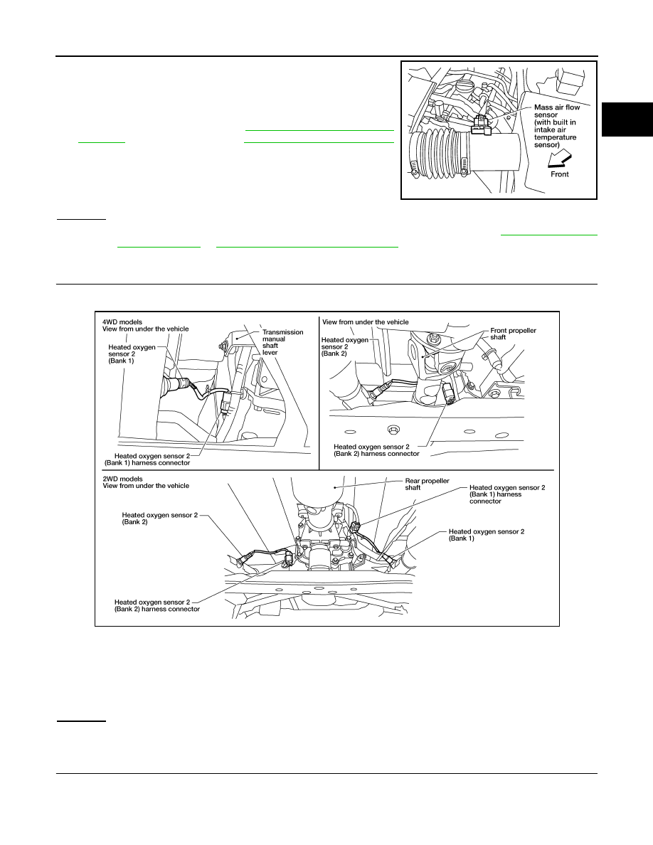
3. Disconnect mass air flow sensor harness connector, and restart

and run engine for at least 5 seconds at idle speed.

4. Stop engine and reconnect mass air flow sensor harness con-

nector.

5. Check DTC P0102 is displayed.

6. Erase the DTC memory. Refer to 

EC-515, "On Board Diagnosis

Function"

 (Without CONSULT) or 

EC-518, "CONSULT Function"

(With CONSULT).

7. Check DTC P0000 is displayed.

8. Run engine for at least 10 minutes at idle speed.

Is the 1st trip DTC P0171, P0172, P0174 or P0175 detected?

Is it difficult to start engine?

Yes or No

Yes

>> Perform trouble diagnosis for DTC P0171, P0174 or P0172, P0175. Refer to 

EC-700, "On Board

Diagnosis Logic"

 or 

EC-706, "On Board Diagnosis Logic"

.

No

>> GO TO 3.

3.

CHECK HO2S2 GROUND CIRCUIT FOR OPEN AND SHORT

1. Turn ignition switch OFF.

2. Disconnect heated oxygen sensor 2 harness connector.

3. Disconnect ECM harness connector.

4. Check harness continuity between HO2S2 terminal 1 and ECM terminal 59.

Refer to Wiring Diagram.

5. Also check harness for short to ground and short to power.
OK or NG

OK

>> GO TO 4.

NG

>> Repair open circuit or short to ground or short to power in harness or connectors.

4.

CHECK HO2S2 INPUT SIGNAL CIRCUIT FOR OPEN AND SHORT

1. Check harness continuity between ECM terminal and HO2S2 terminal as follows.

Refer to Wiring Diagram.

BBIA0541E

Continuity should exist.

BBIA0540E

EC-692

< DTC/CIRCUIT DIAGNOSIS >

[VQ40DE FOR USA AND CANADA]

P0139, P0159 HO2S2

2. Check harness continuity between the following terminals and ground.

Refer to Wiring Diagram.

3. Also check harness for short to power.
OK or NG

OK

>> GO TO 5.

NG

>> Repair open circuit or short to ground or short to power in harness or connectors.

5.

CHECK HEATED OXYGEN SENSOR 2

Refer to 

EC-692, "Component Inspection"

.

OK or NG

OK

>> GO TO 6.

NG

>> Replace malfunctioning heated oxygen sensor 2. Refer to 

EX-5, "Exploded View"

.

6.

CHECK INTERMITTENT INCIDENT

Refer to 

GI-42, "Intermittent Incident"

.

>> INSPECTION END

Component Inspection

INFOID:0000000009481356

HEATED OXYGEN SENSOR 2

 With CONSULT

1. Turn ignition switch ON and select “DATA MONITOR” mode with CONSULT.
2. Start engine and warm it up to the normal operating temperature.
3. Turn ignition switch OFF and wait at least 10 seconds.
4. Start engine and keep the engine speed between 3,500 and 4,000 rpm for at least 1 minute under no load.
5. Let engine idle for 1 minute.
6. Select “FUEL INJECTION” in “ACTIVE TEST” mode, and select “HO2S2 (B1)/(B2)” as the monitor item

with CONSULT.

DTC

Terminals

Bank

ECM

Sensor

P0139

57

2

1

P0159

58

2

2

Continuity should exist.

DTC

Terminals

Bank

ECM

Sensor

P0139

57

2

1

P0159

58

2

2

Continuity should not exist.

P0139, P0159 HO2S2

EC-693

< DTC/CIRCUIT DIAGNOSIS >

[VQ40DE FOR USA AND CANADA]

C

D

E

F

G

H

I

J

K

L

M

A

EC

N

P

O

7. Check “HO2S2 (B1)/(B2)” at idle speed when adjusting “FUEL INJECTION” to 

±25%.

“HO2S2 (B1)/(B2)” should be above 0.71V at least once when the “FUEL INJECTION” is +25%.

“HO2S2 (B1)/(B2)” should be below 0.18V at least once when the “FUEL INJECTION” is 

25%.

CAUTION:

• Discard any heated oxygen sensor which has been dropped from a height of more than 0.5 m (19.7

in) onto a hard surface such as a concrete floor; use a new one.

• Before installing new oxygen sensor, clean exhaust system threads using Oxygen Sensor Thread

Cleaner tool J-43897-18 or J-43897-12 and approved anti-seize lubricant.

 Without CONSULT

1. Start engine and warm it up to the normal operating temperature.
2. Turn ignition switch OFF and wait at least 10 seconds.
3. Start engine and keep the engine speed between 3,500 and 4,000 rpm for at least 1 minute under no load.
4. Let engine idle for 1 minute.
5. Set voltmeter probes between ECM terminal 57 [HO2S2 (B1) signal] or 58 [HO2S2 (B2) signal] and

ground.

6. Check the voltage when revving up to 4,000 rpm under no load at least 10 times.

(Depress and release accelerator pedal as soon as possible.)

The voltage should be above 0.71V at least once during this procedure.

If the voltage is above 0.71V at step 6, step 7 is not necessary.

7. Keep vehicle at idling for 10 minutes, then check voltage. Or check the voltage when coasting from 80 km/

h (50 MPH) in D position with “OD” OFF (A/T), 5th gear position (M/T).

The voltage should be below 0.18V at least once during this procedure.

8. If NG, replace heated oxygen sensor 2. Refer to 

EX-5, "Exploded View"

.

CAUTION:

• Discard any heated oxygen sensor which has been dropped from a height of more than 0.5 m (19.7

in) onto a hard surface such as a concrete floor; use a new one.

• Before installing new oxygen sensor, clean exhaust system threads using Oxygen Sensor Thread

Cleaner tool J-43897-18 or J-43897-12 and approved anti-seize lubricant.

JSBIA1351GB

EC-694

< DTC/CIRCUIT DIAGNOSIS >

[VQ40DE FOR USA AND CANADA]

P014C, P014D, P014E, P014F, P015A, P015B, P015C, P015D A/F SENSOR 1

P014C, P014D, P014E, P014F, P015A, P015B, P015C, P015D A/F SENSOR
1

DTC Logic

INFOID:0000000010232190

DTC DETECTION LOGIC

To judge malfunctions, this diagnosis measures response time of the A/F signal computed by ECM from the A/

F sensor 1 signal. The time is compensated by engine operating (speed and load), fuel feedback control con-

stant, and the A/F sensor 1 temperature index. Judgment is based on whether the compensated time (the A/F

signal cycling time index) is inordinately long or not.

DTC CONFIRMATION PROCEDURE

1.

PRECONDITIONING

If DTC Confirmation Procedure has been previously conducted, always perform the following procedure

before conducting the next test.

1. Turn ignition switch OFF and wait at least 10 seconds.

2. Turn ignition switch ON.

3. Turn ignition switch OFF and wait at least 10 seconds.

TESTING CONDITION:

Before performing the following procedure, confirm that battery voltage is more than 11 V at idle.
Do you have CONSULT?

YES

>> GO TO 2.

NO

>> GO TO 6.

2.

PERFORM DTC CONFIRMATION PROCEDURE-1

With CONSULT

1. Start engine and warm it up to normal operating temperature.

2. Turn ignition switch OFF and wait at least 10 seconds.

3. Turn ignition switch ON.

4. Turn ignition switch OFF and wait at least 10 seconds.

DTC No.

CONSULT screen terms

(Trouble diagnosis content)

DTC detecting condition

Possible Cause

P014C

A/F SENSOR1 (B1)
(O2 sensor slow response - rich 
to lean bank 1 sensor 1)

• The response time of a A/F sensor 1 signal 

delays more than the specified time com-
puted by ECM.

• Harness or connectors

(The A/F sensor 1 circuit is open or 
shorted.)

• A/F sensor 1

P014D

A/F SENSOR1 (B1)
(O2 sensor slow response - lean 
to rich bank 1 sensor 1)

P014E

A/F SENSOR1 (B2)
(O2 sensor slow response - rich 
to lean bank 2 sensor 1)

P014F

A/F SENSOR1 (B2)
(O2 sensor slow response - lean 
to rich bank 2 sensor 1)

P015A

A/F SENSOR1 (B1)
(O2 sensor delayed response - 
rich to lean bank 1 sensor 1)

P015B

A/F SENSOR1 (B1)
(O2 sensor delayed response - 
lean to rich bank 1 sensor 1)

P015C

A/F SENSOR1 (B2)
(O2 sensor delayed response - 
rich to lean bank 2 sensor 1)

P015D

A/F SENSOR1 (B2)
(O2 sensor delayed response - 
lean to rich bank 2 sensor 1)


Content   ..  528  529  530  531   ..