Nissan Frontier. Manual - part 502
DIAGNOSIS AND REPAIR WORKFLOW
EC-579
< BASIC INSPECTION >
[VQ40DE FOR USA AND CANADA]
C
D
E
F
G
H
I
J
K
L
M
A
EC
N
P
O
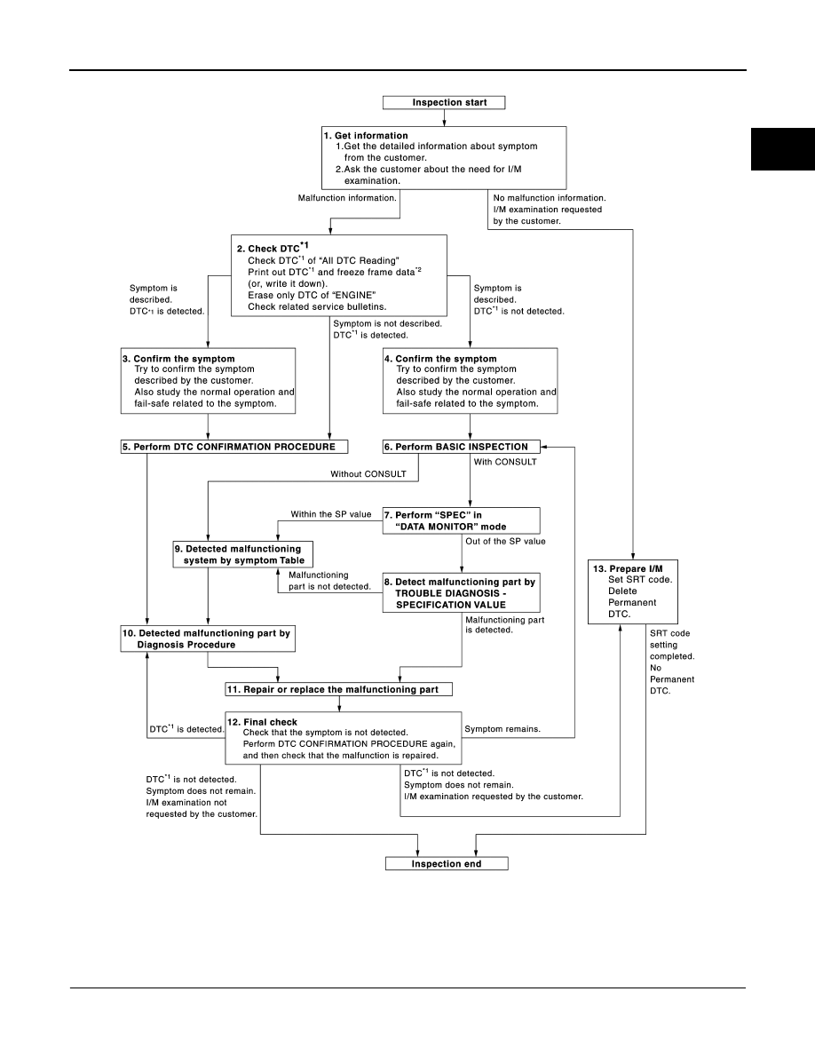
Detailed Flow
1.
GET INFORMATION FOR SYMPTOM
*1: Include 1st trip DTC.
*2: Include 1st trip freeze frame data.
JSBIA0123GB