Nissan Frontier. Manual - part 473
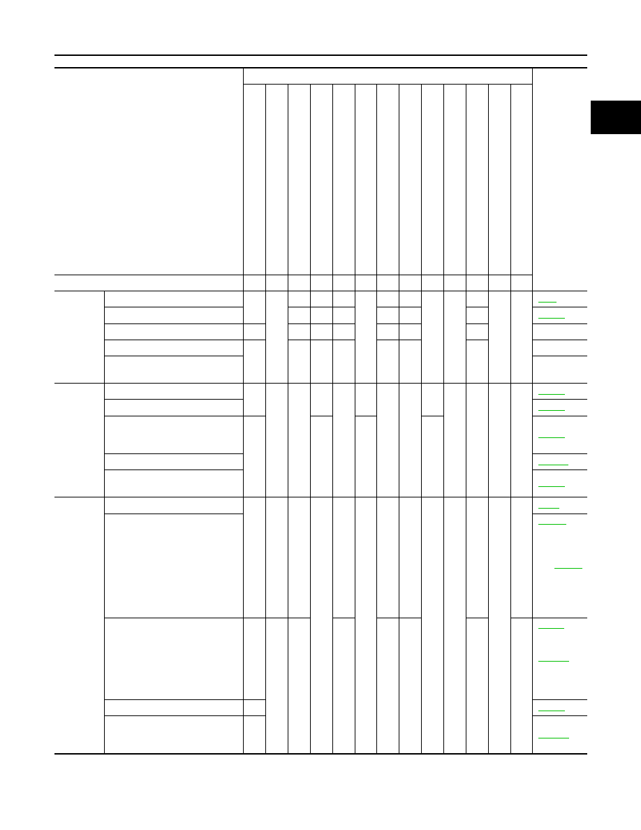
ENGINE CONTROL SYSTEM SYMPTOMS
EC-463
< SYMPTOM DIAGNOSIS >
[QR25DE]
C
D
E
F
G
H
I
J
K
L
M
A
EC
N
P
O
SYMPTOM
Reference
page
HARD/NO ST
AR
T/REST
AR
T (EXCP
.
HA)
E
N
GI
N
E
ST
AL
L
HESIT
A
TION/S
U
R
GING/F
LA
T SP
OT
SP
ARK KNOCK/DE
T
O
NA
TION
LACK OF POWE
R/POOR
ACCELERA
TIO
N
HIGH IDL
E/L
OW
IDL
E
ROUG
H IDLE/HU
NTING
IDL
ING VIBRA
T
ION
SLO
W
/NO RETURN T
O
IDLE
OVERHEA
T
S/W
A
TE
R
TEMPERA
T
URE
HIGH
EXCES
SIVE F
U
EL CONSUMP
T
ION
EXCES
SIVE OI
L CONSUMP
T
IO
N
BA
TTE
R
Y
DEAD (UN
D
E
R
CH
A
R
GE)
Warranty symptom code
AA
AB
AC
AD
AE
AF
AG AH
AJ
AK
AL
AM HA
Fuel
Fuel tank
5
5
Fuel piping
5
5
5
5
5
5
Vapor lock
—
Valve deposit
5
5
5
5
5
5
5
—
Poor fuel (Heavy weight gasoline,
Low octane)
—
Air
Air duct
5
5
5
5
5
5
Air cleaner
Air leakage from air duct
(Mass air flow sensor —electric
throttle control actuator)
5
5
5
5
Electric throttle control actuator
Air leakage from intake manifold/
Collector/Gasket
Cranking
Battery
1
1
1
1
1
1
1
1
Generator circuit
(With EXP-
800 NI or
GR8-1200
NI),
(Without
EXP-800
NI or GR8-
1200 NI)
Starter circuit
3
(With GR8-
1200 NI),
(Without
GR8-1200
NI)
Signal plate/Flywheel/Drive plate
6
Park/neutral position (PNP)
switch (M/T)
TCM (A/T)
4