Nissan Frontier. Manual - part 468


  Index      Nissan     Nissan Frontier (2014 year) - Service and Repair Manual


Search            


Content   ..  466  467  468  469   ..


Nissan Frontier. Manual - part 468


FUEL PUMP

EC-443

< DTC/CIRCUIT DIAGNOSIS >

[QR25DE]

C

D

E

F

G

H

I

J

K

L

M

A

EC

N

P

O

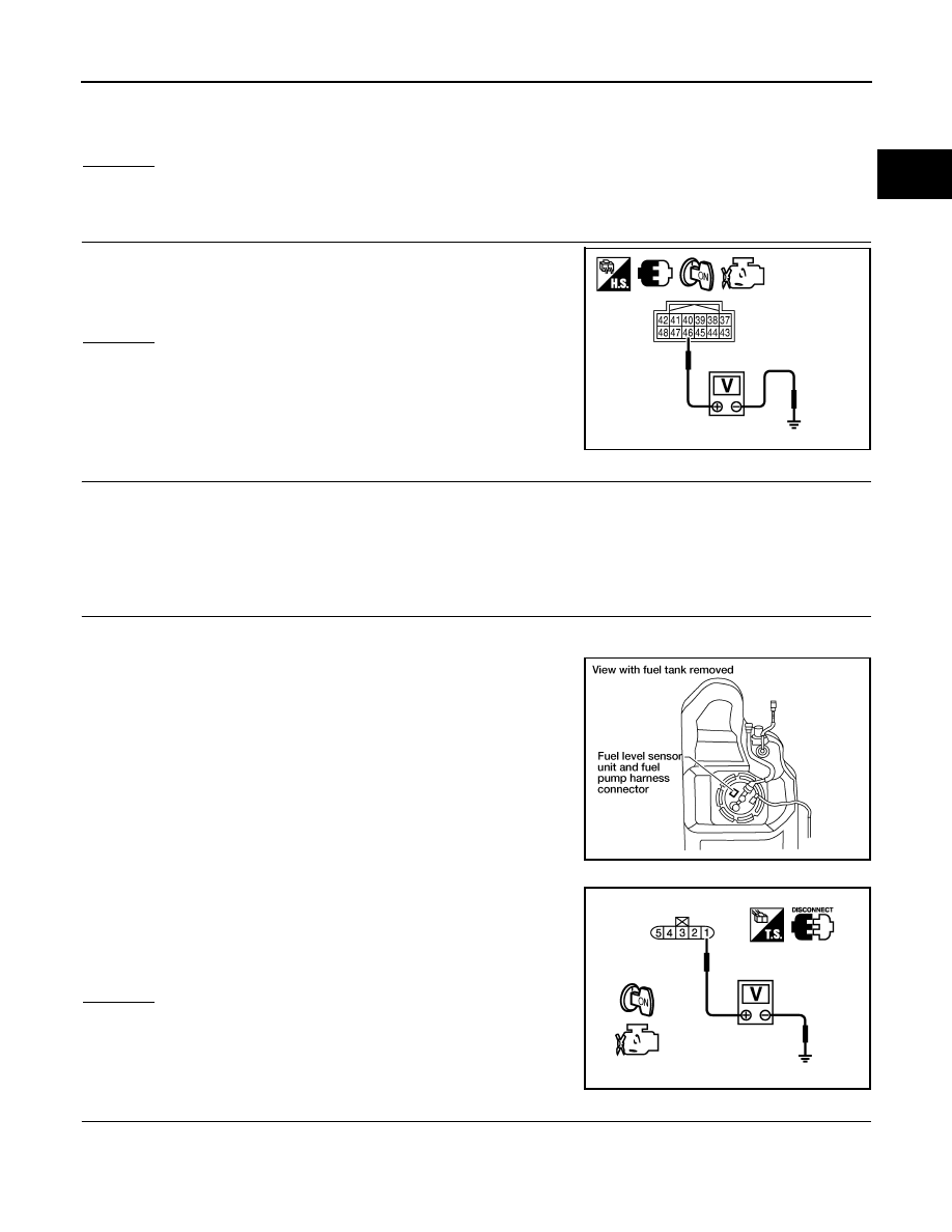
4. Check voltage between ECM terminal 14 and ground with CONSULT or tester.

OK or NG

OK

>> GO TO 5.

NG

>> GO TO 3.

3.

CHECK FUEL PUMP POWER SUPPLY CIRCUIT-II

Check voltage between IPDM E/R terminal 46 and ground with

CONSULT or tester.

OK or NG

OK

>> GO TO 4.

NG

>> GO TO 12.

4.

DETECT MALFUNCTIONING PART

Check the following.

• Harness connectors E5, F14

• Harness for open or short between IPDM E/R and ECM

>> Repair harness or connectors.

5.

CHECK FUEL PUMP POWER SUPPLY CIRCUIT-III

1. Turn ignition switch OFF.

2. Reconnect all harness connectors disconnected.

3. Disconnect “fuel level sensor unit and fuel pump” harness con-

nector.

4. Turn ignition switch ON.

5. Check voltage between “fuel level sensor unit and fuel pump”

terminal 1 and ground with CONSULT or tester. 

OK or NG

OK

>> GO TO 9.

NG

>> GO TO 6.

6.

CHECK 15A FUSE

1. Turn ignition switch OFF.

2. Disconnect 15A fuse (No.48).

3. Check 15A fuse.

Voltage: Battery voltage 

Voltage: Battery voltage

PBIB2656E

BBIA0545E

Voltage:

Battery voltage should exist for 1 second 
after ignition switch is turned ON.

PBIB0795E

EC-444

< DTC/CIRCUIT DIAGNOSIS >

[QR25DE]

FUEL PUMP

OK or NG

OK

>> GO TO 7.

NG

>> Replace fuse.

7.

CHECK FUEL PUMP POWER SUPPLY CURCUIT-IV

1. Disconnect IPDM E/R harness connector E119.

2. Check harness continuity between “fuel level sensor unit and fuel pump” terminal 1 and IPDM E/R termi-

nal 13.

Refer to Wiring Diagram. 

3. Also check harness for short to ground and short to power.
OK or NG

OK

>> GO TO 12.

NG

>> GO TO 8.

8.

DETECT MALFUNCTIONING PART

Check the following.

• Harness connectors C1, E41

• Harness for open or short between “fuel level sensor unit and fuel pump” and IPDM E/R

>> Repair open circuit, short to ground or short to power in harness or connectors.

9.

CHECK FUEL PUMP GROUND CIRCUIT FOR OPEN AND SHORT

1. Check harness continuity between “fuel level sensor unit and fuel pump” terminal 3 and ground.

Refer to Wiring Diagram.

2. Also check harness for short to power.
OK or NG

OK

>> GO TO 11.

NG

>> GO TO 10.

10.

DETECT MALFUNCTIONING PART

Check the following.

• Harness connectors C1, E41

• Harness for open or short between “fuel level sensor unit and fuel pump” and ground

>> Repair open circuit or short to power in harness or connectors.

11.

CHECK FUEL PUMP

Refer to 

EC-444, "Component Inspection"

.

OK or NG

OK

>> GO TO 12.

NG

>> Replace fuel pump. Refer to 

FL-10, "Removal and Installation"

.

12.

CHECK INTERMITTENT INCIDENT

Refer to 

GI-42, "Intermittent Incident"

.

OK or NG

OK

>> Replace IPDM E/R. Refer to 

PCS-28, "Removal and Installation of IPDM E/R"

.

NG

>> Repair or replace harness or connectors.

Component Inspection

INFOID:0000000009481154

FUEL PUMP

Continuity should exist.

Continuity should exist.

FUEL PUMP

EC-445

< DTC/CIRCUIT DIAGNOSIS >

[QR25DE]

C

D

E

F

G

H

I

J

K

L

M

A

EC

N

P

O

1. Disconnect “fuel level sensor unit and fuel pump” harness con-

nector.

2. Check resistance between “fuel level sensor unit and fuel pump”

terminals 1 and 3.

BBIA0545E

Resistance: 0.2 - 5.0

 [at 25°C (77°F)]

SEC918C

EC-446

< DTC/CIRCUIT DIAGNOSIS >

[QR25DE]

IGNITION SIGNAL

IGNITION SIGNAL

Component Description

INFOID:0000000009481155

IGNITION COIL & POWER TRANSISTOR

The ignition signal from the ECM is sent to and amplified by the

power transistor. The power transistor turns ON and OFF the ignition

coil primary circuit. This ON/OFF operation induces the proper high

voltage in the coil secondary circuit.

Diagnosis Procedure

INFOID:0000000009481156

1.

CHECK ENGINE START

Turn ignition switch OFF, and restart engine.

Is engine running?
Yes or No

Yes (With CONSULT)>>GO TO 2.

Yes (Without CONSULT)>>GO TO 3.

No

>> GO TO 4.

2.

CHECK OVERALL FUNCTION

 With CONSULT

1. Perform “POWER BALANCE” in “ACTIVE TEST” mode with CONSULT.

2. Make sure that each circuit produce a momentary engine speed drop.
OK or NG

OK

>> INSPECTION END

NG

>> GO TO 10.

3.

CHECK OVERALL FUNCTION

 Without CONSULT

1. Let engine idle.

2. Read the voltage signal between ECM terminals 9, 10, 11, 21 and ground with an oscilloscope.

3. Verify that the oscilloscope screen shows the signal wave as shown below.

NOTE:

The pulse cycle changes depending on rpm at idle.

OK or NG

OK

>> INSPECTION END

NG

>> GO TO 10.

4.

CHECK IGNITION COIL POWER SUPPLY CIRCUIT-I

1. Turn ignition switch OFF, wait at least 10 seconds and then turn ON.

2. Check voltage between ECM terminals 105 and ground with CONSULT or tester.

BBIA0604E

PBIB0521E

Voltage: Battery voltage


Content   ..  466  467  468  469   ..