Nissan Frontier. Manual - part 458


  Index      Nissan     Nissan Frontier (2014 year) - Service and Repair Manual


Search            


Content   ..  456  457  458  459   ..


Nissan Frontier. Manual - part 458


P2096, P2097 A/F SENSOR 1

EC-403

< DTC/CIRCUIT DIAGNOSIS >

[QR25DE]

C

D

E

F

G

H

I

J

K

L

M

A

EC

N

P

O

 WITH GST

1. Start engine and warm it up to normal operating temperature.

2. Turn ignition switch OFF and wait at least 10 seconds.

3. Disconnect mass air flow sensor harness connector.

4. Start engine and let it idle for at least 5 seconds.

5. Stop engine and reconnect mass air flow sensor harness con-

nector.

6. Select Service $03 with GST and make sure that DTC P0102 is

detected.

7. Select Service $04 with GST and erase the DTC P0102.

8. Start engine and keep the engine speed between 3,500 and

4,000 rpm for 1 minute under no load.

9. Let engine idle for 1 minute.

10. Keep engine speed between 2,500 and 3,000 rpm for 20 min-

utes.

11. Select Service $07 with GST.

If 1st trip DTC is detected, go to 

EC-403, "Diagnosis Procedure"

.

Diagnosis Procedure

INFOID:0000000009481103
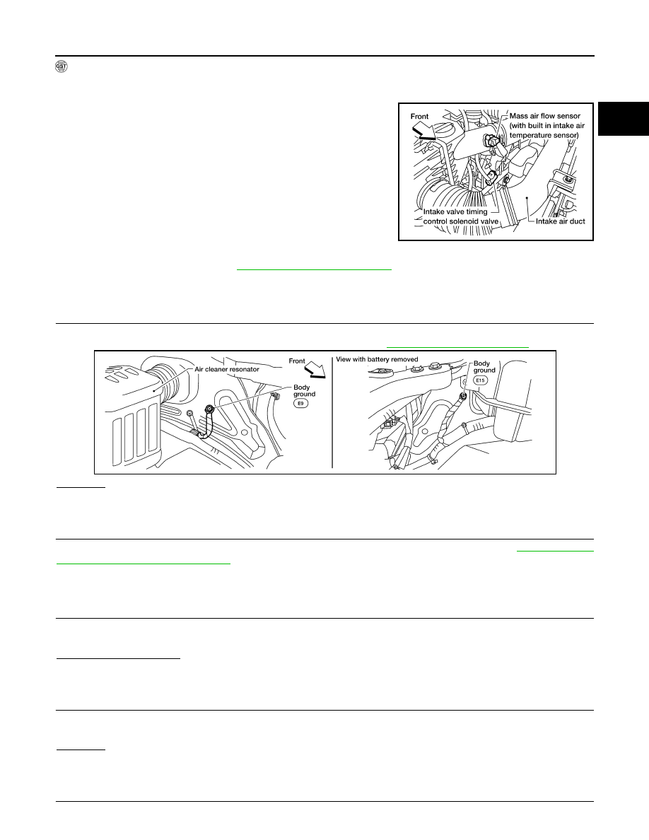
1.

CHECK GROUND CONNECTIONS

1. Turn ignition switch OFF.

2. Loosen and retighten two ground screws on the body. Refer to 

EC-149, "Ground Inspection"

.

OK or NG

OK

>> GO TO 2.

NG

>> Repair or replace ground connections.

2.

RETIGHTEN AIR FUEL RATIO (A/F) SENSOR 1 AND HEATED OXYGEN SENSOR 2

Loosen and retighten the air fuel ratio (A/F) sensor 1 and heated oxygen sensor 2. Refer to 

EC-27, "Engine

Control Component Parts Location"

.

>> GO TO 3.

3.

CHECK FOR EXHAUST GAS LEAK

1. Start engine and run it at idle.

2. Listen for an exhaust gas leak before the three way catalyst 2.
Is exhaust gas detected?

YES

>> Repair or replace.

NO

>> GO TO 4.

4.

CHECK FOR INTAKE AIR LEAK

1. Start engine and run it at idle.

2. Listen for an intake air leak after the mass air flow sensor.
OK or NG

OK

>> GO TO 5.

NG

>> Repair or replace.

5.

CLEAR THE SELF-LEARNING DATA.

BBIA0622E

BBIA0614E

EC-404

< DTC/CIRCUIT DIAGNOSIS >

[QR25DE]

P2096, P2097 A/F SENSOR 1

 With CONSULT

1. Start engine and warm it up to normal operating temperature.

2. Select “SELF-LEARNING CONT” in “WORK SUPPORT” mode with CONSULT.

3. Clear the self-learning control coefficient by touching “CLEAR”.

4. Run engine for at least 10 minutes at idle speed.

Is the 1st trip DTC P0171 or P0172 detected?

Is it difficult to start engine?

 Without CONSULT

1. Start engine and warm it up to normal operating temperature.

2. Turn ignition switch OFF.

3. Disconnect mass air flow sensor harness connector.

4. Restart engine and let it idle for at least 5 seconds.

5. Stop engine and reconnect mass air flow sensor harness con-

nector.

6. Make sure DTC P0102 is displayed.

7. Erase the DTC memory. Refer to 

EC-55, "On Board Diagnosis

Function"

 (Without CONSULT) or 

EC-58, "CONSULT Function"

(With CONSULT).

8. Make sure DTC P0000 is displayed.

9. Run engine for at least 10 minutes at idle speed.

Is the 1st trip DTC P0171 or P0172 detected?

Is it difficult to start engine?

Yes or No

Yes

>> Perform trouble diagnosis for DTC P0171 or P0172. Refer to 

EC-228, "On Board Diagnosis Logic"

or 

EC-233, "On Board Diagnosis Logic"

.

No

>> GO TO 6.

6.

CHECK HARNESS CONNECTOR

1. Turn ignition switch OFF.

2. Disconnect A/F sensor 1 harness connector.

3. Check harness connector for water. 

OK or NG

OK

>> GO TO 7.

NG

>> Repair or replace harness connector.

7.

CHECK AIR FUEL RATIO (A/F) SENSOR 1 POWER SUPPLY CIRCUIT

1. Turn ignition switch ON.

2. Check voltage between A/F sensor 1 terminal 4 and ground with CONSULT or tester.

OK or NG

BBIA0622E

Water should not exit.

BBIA0617E

BBIA0617E

Voltage: Battery voltage

P2096, P2097 A/F SENSOR 1

EC-405

< DTC/CIRCUIT DIAGNOSIS >

[QR25DE]

C

D

E

F

G

H

I

J

K

L

M

A

EC

N

P

O

OK

>> GO TO 9.

NG

>> GO TO 8.

8.

DETECT MALFUNCTIONING PART

Check the following.

• Harness connectors E2, F32

• IPDM E/R harness connector E119

• 15A (No.54)

• Harness for open or short between A/F sensor 1 and fuse

>> Repair or replace harness or connectors.

9.

CHECK A/F SENSOR 1 INPUT SIGNAL CIRCUIT FOR OPEN AND SHORT

1. Turn ignition switch OFF.

2. Disconnect ECM harness connector.

3. Check harness continuity between the following terminals. Refer to Wiring Diagram.

4. Check harness continuity between ECM terminals 45, 49 or A/F sensor 1 terminals 1, 2 and ground. Refer

to Wiring Diagram.

5. Also check harness for short to power.
OK or NG

OK

>> GO TO 10.

NG

>> Repair open circuit, short to ground or short to power in harness or connectors.

10.

CHECK A/F SENSOR 1 HEATER

Refer to 

EC-157, "Component Inspection"

.

OK or NG

OK

>> GO TO 11.

NG

>> GO TO 13.

11.

CHECK HEATED OXYGEN SENSOR 2

Refer to 

EC-210, "Component Inspection"

.

Is the inspection result normal?

YES

>> GO TO 12.

NO

>> Replace heated oxygen sensor 2. Refer to 

EC-27, "Engine Control Component Parts Location"

.

12.

CHECK INTERMITTENT INCIDENT

Perfor

GI-42, "Intermittent Incident"

.

OK or NG

OK

>> GO TO 13.

NG

>> Repair or replace.

13.

REPLACE AIR FUEL RATIO (A/F) SENSOR 1

Replace air fuel ratio (A/F) sensor 1. Refer to 

EM-31, "Exploded View"

.

CAUTION:

• Discard any air fuel ratio (A/F) sensor which has been dropped from a height of more than 0.5 m

(19.7 in) onto a hard surface such as a concrete floor; use a new one.

A/F sensor 1 terminal

ECM terminal

1

45

2

49

Continuity should exist.

Continuity should not exist.

EC-406

< DTC/CIRCUIT DIAGNOSIS >

[QR25DE]

P2096, P2097 A/F SENSOR 1

• Before installing new air fuel ratio (A/F) sensor, clean exhaust system threads using Heated Oxygen

Sensor Thread Cleaner [commercial service tool (J-43897-18 or J-43897-12)] and approved anti-seize

lubricant (commercial service tool).

>> GO TO 14.

14.

CONFIRM A/F ADJUSTMENT DATA

1. Turn ignition switch ON.

2. Select “A/F ADJ-B1” in “DATA MONITOR” mode with CONSULT.

3. Make sure that “0.000” is displayed on CONSULT screen.
OK or NG

OK

>> INSPECTION END.

NG

>> GO TO 15.

15.

CLEAR THE SELF-LEARNING DATA

 With CONSULT

1. Start engine and warm it up to normal operating temperature.

2. Select “SELF-LEARNING CONT” in “WORK SUPPORT” mode with CONSULT.

3. Clear the self-learning control coefficient by touching “CLEAR”.

 Without CONSULT

1. Start engine and warm it up to normal operating temperature.

2. Turn ignition switch OFF.

3. Disconnect mass air flow sensor harness connector.

4. Restart engine and let it idle for at least 5 seconds.

5. Stop engine and reconnect mass air flow sensor harness con-

nector.

6. Make sure DTC P0102 is displayed.

7. Erase the DTC memory. Refer to 

EC-55, "On Board Diagnosis

Function"

 (Without CONSULT) or 

EC-58, "CONSULT Function"

(With CONSULT).

8. Make sure DTC P0000 is displayed.

>> GO TO 16.

16.

CONFIRM A/F ADJUSTMENT DATA

1. Turn ignition switch OFF and then ON.

2. Select “A/F ADJ-B1” in “DATA MONITOR” mode with CONSULT.

3. Make sure that “0.000” is displayed on CONSULT screen.

>> INSPECTION END

BBIA0622E


Content   ..  456  457  458  459   ..