Nissan Frontier. Manual - part 426
P0442 EVAP CONTROL SYSTEM
EC-275
< DTC/CIRCUIT DIAGNOSIS >
[QR25DE]
C
D
E
F
G
H
I
J
K
L
M
A
EC
N
P
O
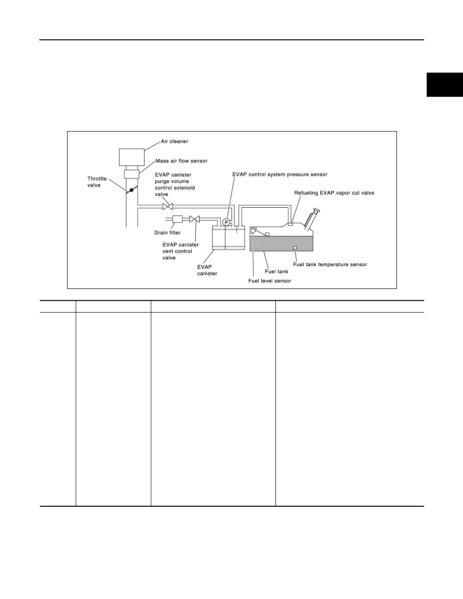
P0442 EVAP CONTROL SYSTEM
On Board Diagnosis Logic
INFOID:0000000009480935
This diagnosis detects leaks in the EVAP purge line using engine intake manifold vacuum.
If pressure does not increase, the ECM will check for leaks in the line between the fuel tank and EVAP canister
purge volume control solenoid valve, under the following Vacuum test conditions.
The EVAP canister vent control valve is closed to shut the EVAP purge line off. The EVAP canister purge vol-
ume control solenoid valve will then be opened to depressurize the EVAP purge line using intake manifold
vacuum. After this occurs, the EVAP canister purge volume control solenoid valve will be closed.
CAUTION:
• Use only a genuine NISSAN fuel filler cap as a replacement. If an incorrect fuel filler cap is used, the
MIL may illuminate.
• If the fuel filler cap is not tightened properly, the MIL may illuminate.
• Use only a genuine NISSAN rubber tube as a replacement.
PBIB3640E
DTC No.
Trouble diagnosis name
DTC detecting condition
Possible cause
P0442
0442
EVAP control system
small leak detected
(negative pressure)
EVAP control system has a leak, EVAP
control system does not operate properly.
• Incorrect fuel tank vacuum relief valve
• Incorrect fuel filler cap used
• Fuel filler cap remains open or fails to close.
• Foreign matter caught in fuel filler cap.
• Leak is in line between intake manifold and
EVAP canister purge volume control solenoid
valve.
• Foreign matter caught in EVAP canister vent
control valve.
• EVAP canister or fuel tank leaks
• EVAP purge line (pipe and rubber tube) leaks
• EVAP purge line rubber tube bent
• Loose or disconnected rubber tube
• EVAP canister vent control valve and the circuit
• EVAP canister purge volume control solenoid
valve and the circuit
• Fuel tank temperature sensor
• O-ring of EVAP canister vent control valve is
missing or damaged
• EVAP canister is saturated with water
• EVAP control system pressure sensor
• Fuel level sensor and the circuit
• Refueling EVAP vapor cut valve
• ORVR system leaks