Nissan Frontier. Manual - part 394
POWER SUPPLY AND GROUND CIRCUIT
EC-147
< DTC/CIRCUIT DIAGNOSIS >
[QR25DE]
C
D
E
F
G
H
I
J
K
L
M
A
EC
N
P
O
6.
DETECT MALFUNCTIONING PART
Check the following.
• Harness connectors F32, E2
• Harness for open or short between ECM and ground
>> Repair open circuit or short to power in harness or connectors.
7.
CHECK ECM POWER SUPPLY CIRCUIT-II
1. Reconnect ECM harness connector.
2. Turn ignition switch ON.
3. Check voltage between IPDM E/R connector E119 terminal 3
and ground with CONSULT or tester.
OK or NG
OK
>> Go to
.
NG
>> GO TO 8.
8.
CHECK ECM POWER SUPPLY CIRCUIT-III
1. Turn ignition switch OFF and wait at least 10 seconds.
2. Turn ignition switch ON and then OFF.
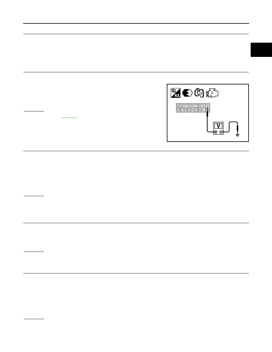
3. Check voltage between ECM terminals 105 and ground with CONSULT or tester.
OK or NG
OK
>> GO TO 13.
NG (Battery voltage does not exist.)>>GO TO 9.
NG (Battery voltage exists for more than a few seconds.)>>GO TO 11.
9.
CHECK ECM POWER SUPPLY CIRCUIT-IV
1. Turn ignition switch OFF and wait at least 10 seconds.
2. Check voltage between ECM terminal 24 and ground with CONSULT or tester.
OK or NG
OK
>> GO TO 10.
NG
>> GO TO 11.
10.
CHECK ECM POWER SUPPLY CIRCUIT-V
1. Disconnect ECM harness connector.
2. Disconnect IPDM E/R harness connector E119.
3. Check harness continuity between ECM terminals 105 and IPDM E/R terminal 4.
Refer to Wiring Diagram.
4. Also check harness for short to ground and short to power.
OK or NG
OK
>> GO TO 16.
NG
>> Repair open circuit, short to ground or short to power in harness or connectors.
Voltage: Battery voltage
PBIB2658E
Voltage:
After turning ignition switch OFF, battery
voltage will exist for a few seconds, then drop
to approximately 0V.
Voltage: Battery voltage
Continuity should exist.