Nissan Frontier. Manual - part 345
DLN-282
< DTC/CIRCUIT DIAGNOSIS >
[REAR FINAL DRIVE: M226 (ELD) ]
P1838 ON SWITCH
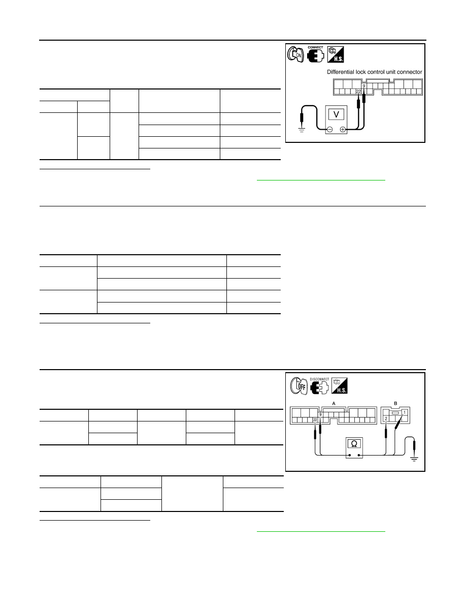
1. Turn ignition switch OFF.
2. Connect differential lock mode switch harness connector.
3. Check voltage between differential lock control unit harness
connector M70 terminals 9, 22 and ground.
Is the inspection result normal?
YES
>> Replace the differential lock control unit. Refer to
DLN-311, "Removal and Installation"
.
NO
>> GO TO 4.
4.
CHECK DIFFERENTIAL LOCK MODE SWITCH
1. Turn ignition switch OFF.
2. Disconnect differential lock mode switch harness connector.
3. Operate differential lock mode switch and check continuity between differential lock mode switch termi-
nals.
Is the inspection result normal?
YES
>> GO TO 5.
NO
>> Replace differential lock mode switch.
5.
CHECK HARNESS BETWEEN DIFFERENTIAL LOCK CONTROL UNIT AND DIFFERENTIAL LOCK
MODE SWITCH
1. Check continuity between differential lock control unit harness
connector M70 (A) terminals 9, 22 and differential lock mode
switch harness connector M149 (B) terminals 2, 1.
2. Check continuity between differential lock control unit harness
connector M70 (A) terminals 9, 22 and ground.
Is the inspection result normal?
YES >> Replace the differential lock control unit. Refer to
DLN-311, "Removal and Installation"
.
NO
>> Repair harness or connector.
(+)
(-)
Differential lock mode
switch
Voltage (Approx.)
Connector
Terminal
M70
9
Ground
ON
Battery voltage
OFF
0V
22
ON
0V
OFF
Battery voltage
SDIA2568E
Terminals
Differential lock mode switch
Continuity
1 - 3
ON
No
OFF
Yes
2 - 3
ON
Yes
OFF
No
Connector
Terminal
Connector
Terminal
Continuity
M70 (A)
9
M149 (B)
2
Yes
22
1
Connector
Terminal
Ground
Continuity
M70 (A)
9
No
22
ALDIA0165ZZ