Nissan Frontier. Manual - part 283


  Index      Nissan     Nissan Frontier (2014 year) - Service and Repair Manual


Search            


Content   ..  281  282  283  284   ..


Nissan Frontier. Manual - part 283


DLN-34

< DTC/CIRCUIT DIAGNOSIS >

[TRANSFER: TX15B]

P1814 WAIT DETECTION SWITCH

P1814 WAIT DETECTION SWITCH

Description

INFOID:0000000009479655

The wait detection switch detects if the transfer case is in 4WD. DTC P1814 will set if an improper signal from

the wait detection switch is input due to open or short circuit.

DTC Logic

INFOID:0000000009479656

DTC DETECTION LOGIC

DTC CONFIRMATION PROCEDURE

1.

DTC CONFIRMATION PROCEDURE

1. Turn ignition switch ON.

2. Perform self-diagnosis.
Is DTC P1814 detected?

YES

>> Perform diagnosis procedure. Refer to 

DLN-34, "Diagnosis Procedure"

.

NO

>> Inspection End.

Diagnosis Procedure

INFOID:0000000009479657

Regarding Wiring Diagram information, refer to 

DLN-63, "Wiring Diagram"

.

1.

CHECK WAIT DETECTION SWITCH SIGNAL

With CONSULT

1. Start engine.

2. Select “DATA MONITOR” mode for “ALL MODE AWD/4WD” with CONSULT.

3. Read out the value of “WAIT DETCT SW”.
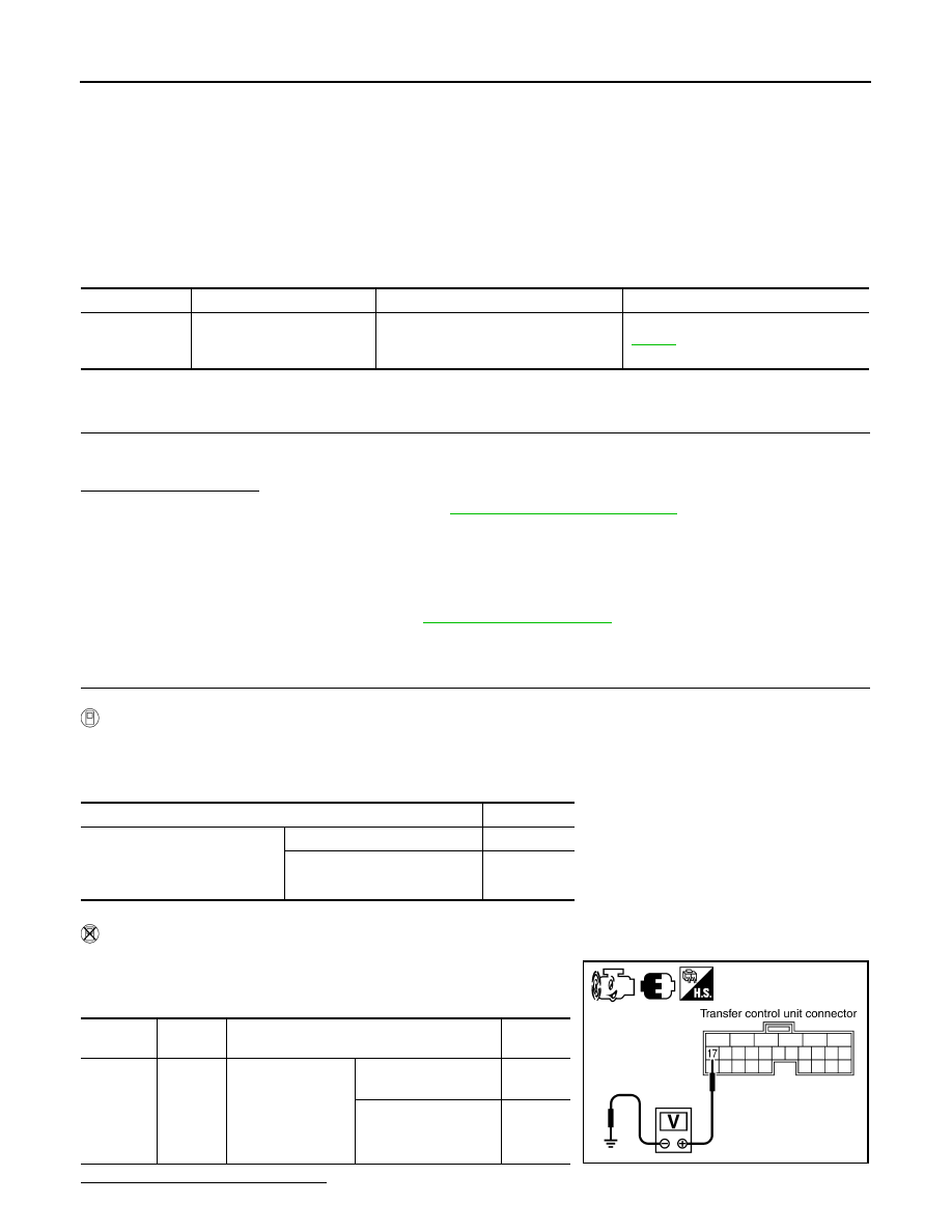
Without CONSULT

1. Start engine.

2. Check voltage between transfer control unit harness connector

terminal and ground.

Are the inspection results normal?

DTC

CONSULT

Diagnostic item is detected when...

Reference

[P1814]

4WD DETECT SWITCH

Improper signal from wait detection 
switch is input due to open or short cir-
cuit.

DLN-34

Condition

Display value

• Vehicle stopped
• Engine running
• A/T selector lever “N” position
• Brake pedal depressed

4WD shift switch: 4H and 4LO

ON

4WD shift switch: 2WD

OFF

Connector

Terminal

Condition

Voltage 

(Approx.)

M152

17 - 

Ground

• Vehicle stopped
• Engine running
• A/T selector lever 

“N” position

• Brake pedal de-

pressed

4WD shift switch
: 4H and 4LO

0V

4WD shift switch: 2WD

Battery 
voltage

SDIA3367E

P1814 WAIT DETECTION SWITCH

DLN-35

< DTC/CIRCUIT DIAGNOSIS >

[TRANSFER: TX15B]

C

E

F

G

H

I

J

K

L

M

A

B

DLN

N

O

P

YES 

>> GO TO 5.

NO

>> GO TO 2.

2.

CHECK HARNESS BETWEEN TRANSFER CONTROL UNIT AND WAIT DETECTION SWITCH

1. Turn ignition switch “OFF”. (Stay for at least 5 seconds.)

2. Disconnect transfer control unit harness connector and the wait detection switch harness connector.

3. Check continuity between transfer control unit harness connec-

tor M152 terminal 17 and wait detection switch harness connec-

tor F59 terminal 10.

Also check harness for short to ground and short to power.

Is there continuity?

YES

>> GO TO 3.

NO

>> Repair or replace damaged parts.

3.

CHECK GROUND CIRCUIT

1. Turn ignition switch “OFF”. (Stay for at least 5 seconds.)

2. Disconnect wait detection switch harness connector.

3. Check continuity between wait detection switch harness con-

nector F59 terminal 11 and ground.

Also check harness for short to power.

Is there continuity?

 YES  >> GO TO 4.

 NO

>> Repair open circuit or short to power in harness or con-

nectors.

4.

CHECK WAIT DETECTION SWITCH 

1. Turn ignition switch “OFF”. (Stay for at least 5 seconds.)

2. Disconnect wait detection switch harness connector.

3. Remove wait detection switch. Refer to 

DLN-13, "Component Parts Location"

.

4. Push and release wait detection switch and check continuity between wait detection switch terminals 10

and 11.

Are the inspection results normal?

YES

>> GO TO 5.

NO

>> Replace wait detection switch.

5.

CHECK TRANSFER CONTROL UNIT

Check transfer control unit input/output signal. Refer to 

DLN-56, "Reference Value"

.

Are the inspection results normal?

YES

>> GO TO 6.

NO

>> Check transfer control unit pin terminals for damage or loose connection with harness connector.

If any items are damaged, repair or replace damaged parts.

6.

CHECK DTC

Drive the vehicle and then perform self-diagnosis.
Is DTC P1814 displayed?

YES

>> Replace transfer control unit. Refer to 

DLN-92, "Removal and Installation"

.

Continuity should exist.

SDIA3368E

Continuity should exist.

PDIA0207E

Terminal

Condition

Continuity

10 - 11

Push wait detection switch

Yes

Release wait detection switch

No

DLN-36

< DTC/CIRCUIT DIAGNOSIS >

[TRANSFER: TX15B]

P1814 WAIT DETECTION SWITCH

NO

>> Inspection End.

Component Inspection

INFOID:0000000009479658

1. Turn ignition switch “OFF”. (Stay for at least 5 seconds.)
2. Disconnect wait detection switch harness connector.
3. Remove wait detection switch. Refer to 

DLN-13, "Component Parts Location"

.

4. Push and release wait detection switch and check continuity between wait detection switch terminals 10

and 11.

5. If the inspection results are abnormal replace the wait detection switch.

Terminal

Condition

Continuity

10 - 11

Push wait detection switch

Yes

Release wait detection switch

No

P1816 PNP SWITCH (A/T)

DLN-37

< DTC/CIRCUIT DIAGNOSIS >

[TRANSFER: TX15B]

C

E

F

G

H

I

J

K

L

M

A

B

DLN

N

O

P

P1816 PNP SWITCH (A/T)

Description

INFOID:0000000009479659

The transmission range switch transmits the A/T position indicator signal (transmission range switch signal)

via CAN communication to the transfer control unit. DTC P1816 will set when the transmission range switch

signal is malfunctioning or there is a communication error.

DTC Logic

INFOID:0000000009479660

DTC DETECTION LOGIC

DTC CONFIRMATION PROCEDURE

1.

DTC CONFIRMATION PROCEDURE

1. Turn ignition switch ON.

2. Perform self-diagnosis.
Is DTC P1816 displayed?

YES

>> Perform diagnosis procedure. Refer to 

DLN-37, "Diagnosis Procedure"

.

NO

>> Inspection End.

Diagnosis Procedure

INFOID:0000000009479661

1.

CHECK DTC WITH TCM

Perform self-diagnosis with TCM. Refer to 

TM-157, "CONSULT Function (TRANSMISSION)"

.

Is any malfunction detected by self-diagnosis?

YES

>> Check the malfunctioning system.

NO

>> GO TO 2.

2.

CHECK TRANSFER CONTROL UNIT

Check transfer control unit input/output signal. Refer to 

DLN-56, "Reference Value"

.

Is the inspection result normal?

YES

>> GO TO 3.

NO

>> Check transfer control unit pin terminals for damage or loose connection with harness connector.

If any items are damaged, repair or replace damaged parts.

3.

CHECK DTC

Drive the vehicle and then perform self-diagnosis.
Is DTC P1816 displayed?

YES

>> Perform self-diagnosis with TCM again.

NO

>> Inspection End.

DTC

CONSULT

Diagnostic item is detected when...

Reference

[P1816]

PNP SW/CIRC

When transmission range switch signal 
is malfunction or communication error 
between the control units.

DLN-37


Content   ..  281  282  283  284   ..