Nissan Frontier. Manual - part 251
DLK-50
< DTC/CIRCUIT DIAGNOSIS >
REMOTE KEYLESS ENTRY RECEIVER
Is the inspection result normal?
YES
>> GO TO 2
NO
>> GO TO 4
2.
REMOTE KEYLESS ENTRY RECEIVER 5-VOLT CIRCUIT INSPECTION
Check voltage between remote keyless entry receiver connector
M120 terminal 4 and ground.
Is the inspection result normal?
YES
>> GO TO 3
NO
>> GO TO 4
3.
REMOTE KEYLESS ENTRY RECEIVER GROUND CIRCUIT INSPECTION
Check continuity between remote keyless entry receiver connector
M120 terminal 1 and ground.
Is the inspection result normal?
YES
>> Replace remote keyless entry receiver.
NO
>> GO TO 4
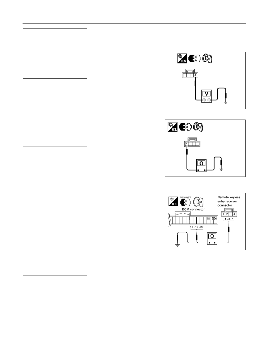
4.
HARNESS INSPECTION BETWEEN BCM AND RKE RECEIVER
1. Disconnect remote keyless entry receiver and BCM connectors.
2. Check continuity between BCM connector M18 terminals 18, 19,
20 and remote keyless entry receiver connector M120 terminals
1, 2, 4.
3. Check continuity between remote keyless entry receiver con-
nector M120 terminals 1, 2, 4 and ground.
Is the inspection result normal?
YES
>> Replace remote keyless entry receiver.
NO
>> Repair or replace the harness between the remote keyless entry receiver and BCM.
4 - Ground
: Approx. 5 volt.
PIIB6458E
1 - Ground
: Continuity should exist.
PIIB6460E
1 - 18
: Continuity should exist.
2 - 20
: Continuity should exist.
4 - 19
: Continuity should exist.
1 - Ground
: Continuity should not exist.
2 - Ground
: Continuity should not exist.
4 - Ground
: Continuity should not exist.
WIIA0308E