Nissan Frontier. Manual - part 220


  Index      Nissan     Nissan Frontier (2014 year) - Service and Repair Manual


Search            


Content   ..  218  219  220  221   ..


Nissan Frontier. Manual - part 220


WATER CONTROL VALVE

CO-27

< REMOVAL AND INSTALLATION >

[QR25DE]

C

D

E

F

G

H

I

J

K

L

M

A

CO

N

P

O

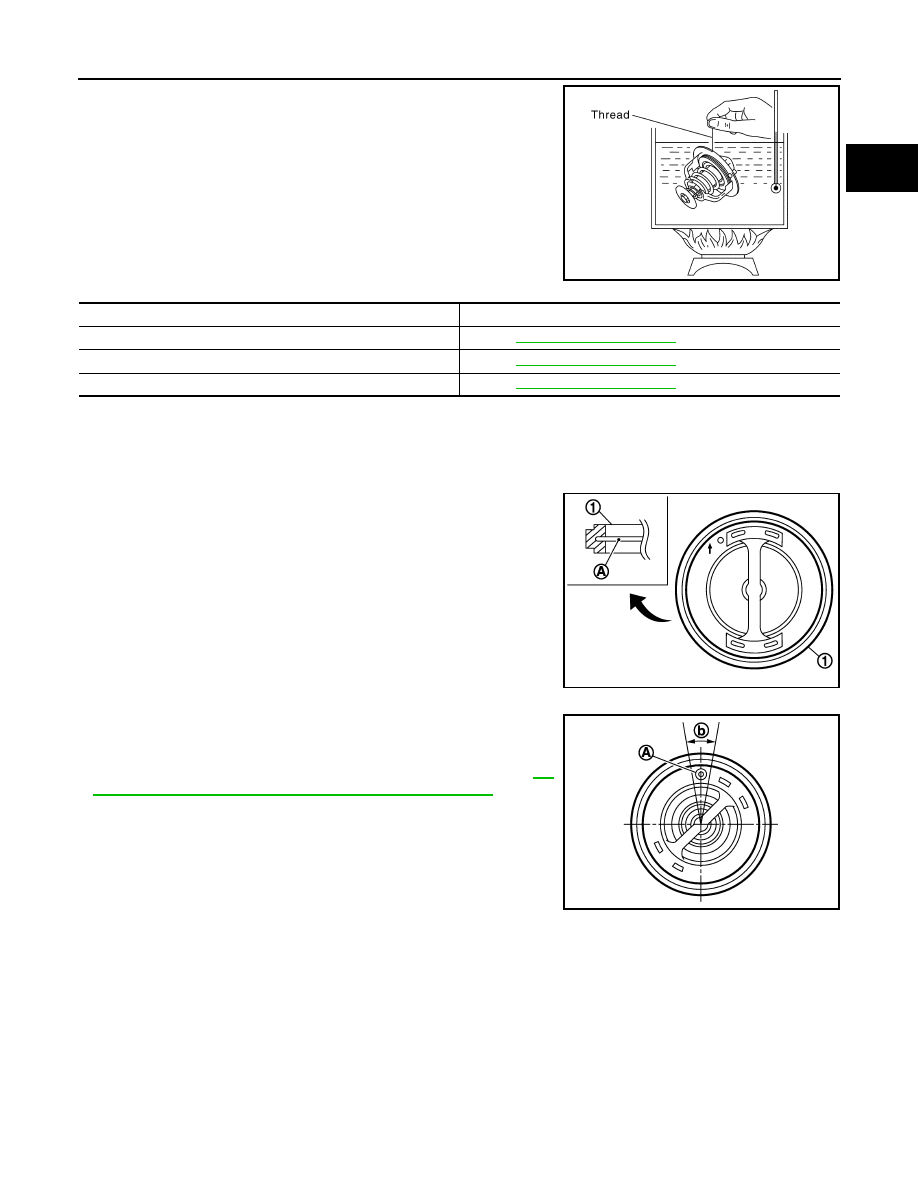
• Place a thread so that it is caught in the valve of the water control

valve. Immerse fully in a container filled with water. Heat while stir-

ring. 

• The valve opening temperature is the temperature at which the

valve opens and the falls from the thread.

• Continue heating. Check the full-open lift amount.

NOTE:

The full-open lift amount standard temperature is the reference

value.

•  After checking the full-open lift amount, lower the water tempera-

ture and check the valve closing temperature. 


If out of the specification range, replace the water control valve. 

INSTALLATION

Installation is in the reverse order of removal.

Water Control Valve

• Install water control valve by making O-ring (1) groove fit to water

control valve flange (A) around the whole circumference.

CAUTION:

Do not reuse O-ring.

• Install water control valve with jiggle valve (A) facing upward. The

position may deviate within the range of 20

° (b).

• Install the engine coolant temperature sensor if removed.

Use Genuine RTV Silicone Sealant or equivalent. Refer to 

GI-

21, "Recommended Chemical Products and Sealants"

.

SLC252B

Water Control Valve 

Standard Value

Valve opening temperature

Refer to 

CO-30, "Standard and Limit"

Full-open lift amount

Refer to 

CO-30, "Standard and Limit"

Valve closing temperature

Refer to 

CO-30, "Standard and Limit"

PBIC3317J

JPBIA2314ZZ

CO-28

< REMOVAL AND INSTALLATION >

[QR25DE]

WATER OUTLET AND WATER PIPING

WATER OUTLET AND WATER PIPING

Exploded View

INFOID:0000000009478174

Removal and Installation

INFOID:0000000009478175

WARNING:

Do not remove the radiator cap when the engine is hot. Serious burns could occur from high pressure

engine coolant escaping from the radiator. Wrap a thick cloth around the cap. Slowly turn it a quarter

of a turn to release built-up pressure. Carefully remove radiator cap by turning it all the way.

NOTE:

When removing components such as hoses, tubes/lines, etc., cap or plug openings to prevent fluid from spill-

ing.

REMOVAL

1. Drain engine coolant from the radiator. Refer to 

CO-12, "Changing Engine Coolant"

.

CAUTION:

• Perform this step when engine is cold.

• Do not spill engine coolant on drive belts.

2. Remove the air duct. Refer to 

EM-25, "Exploded View"

.

3. Disconnect radiator hose (upper) at water outlet side. Refer to 

CO-16, "Exploded View"

.

4. Remove water outlet.
5. Remove throttle body coolant hose at heater pipe.
6. Remove heater core coolant hose at heater pipe.

1.

Gasket

2.

Water outlet

3.

Water pump pulley

4.

Water pump

5.

Thermostat

6.

O-ring

7.

Water inlet

8.

Water pump and thermostat housing 9.

Heater pipe

10. Water hose

11. Water hose

12. Heater outlet

13. Engine coolant temperature sensor

14. Water control valve

A.

To heater

B.

To electric throttle control actuator

C.

To oil cooler

Front

AWBIA0868GB

WATER OUTLET AND WATER PIPING

CO-29

< REMOVAL AND INSTALLATION >

[QR25DE]

C

D

E

F

G

H

I

J

K

L

M

A

CO

N

P

O

7. Remove oil cooler coolant hose at heater pipe.
8. Remove oil level gauge and oil level gauge guide.
9. Remove exhaust manifold heat shield.
10. Remove heater pipe and O-ring.

CAUTION:

Do not reuse O-ring.

INSTALLATION

Installation is in the reverse order of removal.

CAUTION:

Do not reuse O-ring.

• Securely insert each hose, and install clamp at a position where it does not interfere with the pipe bulge.

INSPECTION AFTER INSTALLATION

• Check for engine coolant leaks. Refer to 

CO-11, "System Inspection"

.

• Start and warm up engine. Visually check for engine coolant leaks. Repair as necessary.

CO-30

< SERVICE DATA AND SPECIFICATIONS (SDS) 

[QR25DE]

SERVICE DATA AND SPECIFICATIONS (SDS)

SERVICE DATA AND SPECIFICATIONS (SDS)

SERVICE DATA AND SPECIFICATIONS (SDS)

Standard and Limit

INFOID:0000000009478176

ENGINE COOLANT CAPACITY (APPROXIMATE)

Unit:   (US qt, Imp qt)

RADIATOR

Unit: kPa (kg/cm

2

, psi)

THERMOSTAT

WATER CONTROL VALVE

Engine coolant capacity (With reservoir tank at “MAX” level)

9.4 (10, 8-1/4)

Reservoir cap relief pressure

Standard

98 - 118 (1.0 - 1.2, 14- 17)

Testing pressure

156 (1.6, 23)

Valve opening temperature

80.5 - 83.5

°C (177 - 182°F)

Full-open lift amount

8 mm/ 95

°C (0.315 in/ 203°F)

Valve closing temperature

77

°C (171°F) 

Valve opening temperature

93.5 - 96.5

°C (200 - 206°F)

Full-open lift amount

More than 8 mm/ 108

°C (0.315 in/ 226°F)

Valve closing temperature

90

°C (194°F) or higher


Content   ..  218  219  220  221   ..