Content .. 1334 1335 1336 1337 ..
Nissan Frontier. Manual - part 1336
IPDM E/R (INTELLIGENT POWER DISTRIBUTION MODULE ENGINE ROOM)
WW-39
< ECU DIAGNOSIS INFORMATION >
C
D
E
F
G
H
I
J
K
M
A
B
WW
N
O
P
24
P
Cooling fan motor
(high)
Output
—
Conditions correct for cooling
fan operation
Battery voltage
Conditions not correct for
cooling fan operation
0V
27
W/G
Fuse 38
Output
—
Ignition switch ON or START
Battery voltage
Ignition switch OFF or ACC
0V
28
R
LH front parking and
front side marker lamp
Output
OFF
Lighting
switch 1st po-
sition
OFF
0V
ON
Battery voltage
29
G
Trailer tow relay
Output
ON
Lighting
switch 1st po-
sition
OFF
0V
ON
Battery voltage
30
R/B
Fuse 53
Output
—
Ignition switch ON or START
Battery voltage
Ignition switch OFF or ACC
0V
32
GR
Wiper low speed sig-
nal
Output
ON or
START
Wiper switch
OFF
Battery voltage
LO or INT
0V
35
L
Wiper high speed sig-
nal
Output
ON or
START
Wiper switch
OFF, LO, INT
Battery voltage
HI
0V
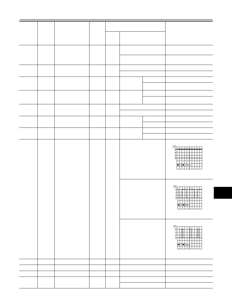
37
Y
Power generation
command signal
Output
—
Ignition switch ON
6.3 V
40% is set on "Active test,"
"ALTERNATOR DUTY" of
"ENGINE"
3.8 V
40% is set on "Active test,"
"ALTERNATOR DUTY" of
"ENGINE"
1.4 V
38
B
Ground
Input
—
—
0V
39
L
CAN-H
—
ON
—
—
40
P
CAN-L
—
ON
—
—
42
GR
Oil pressure switch
Input
—
Engine running
Battery voltage
Engine stopped
0V
Terminal
Wire
color
Signal name
Signal
input/
output
Measuring condition
Reference value
(Approx.)
Igni-
tion
switch
Operation or condition
JPMIA0001GB
JPMIA0002GB
JPMIA0003GB