Nissan Frontier. Manual - part 1329


  Index      Nissan     Nissan Frontier (2014 year) - Service and Repair Manual


Search            


Content   ..  1327  1328  1329  1330   ..


Nissan Frontier. Manual - part 1329


DIAGNOSIS SYSTEM (IPDM E/R)

WW-11

< SYSTEM DESCRIPTION >

C

D

E

F

G

H

I

J

K

M

A

B

WW

N

O

P

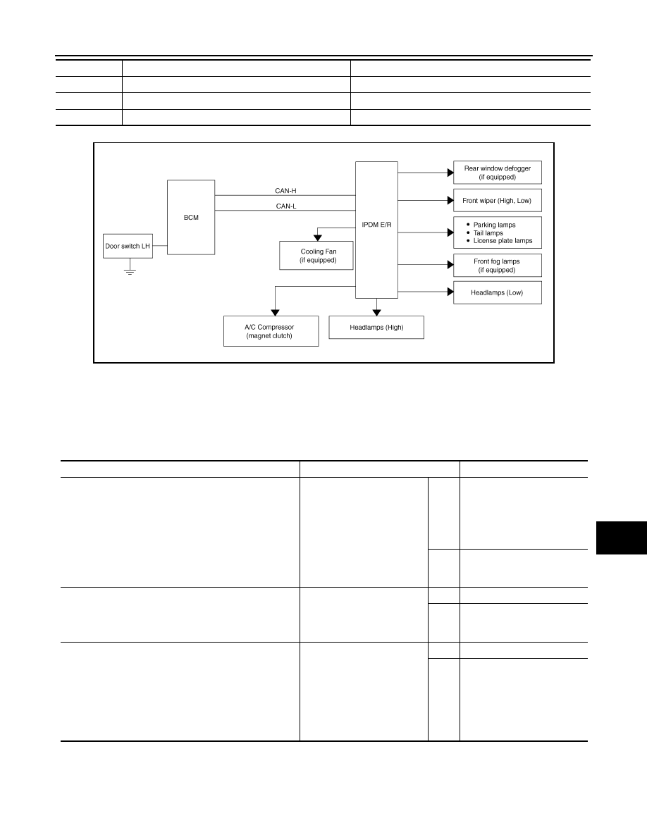
Concept of auto active test

• IPDM E/R starts the auto active test with the door switch signals transmitted by BCM via CAN communica-

tion. Therefore, the CAN communication line between IPDM E/R and BCM is considered normal if the auto

active test starts successfully.

• The auto active test facilitates troubleshooting if any systems controlled by IPDM E/R cannot be operated.

Diagnosis chart in auto active test mode

4

Headlamps 

Low ON for 10 seconds, then High ON-OFF five times.

5

A/C compressor (magnet clutch)

ON-OFF 5 times

6

Cooling fan (if equipped) 

LOW 5 seconds then HIGH 5 seconds

Item Number

Test Item

Operation Time/Frequency

AWMIA1486GB

Symptom

Inspection contents

Possible cause

Oil pressure low warning indicator does not operate

Perform auto active test.
Does the oil pressure low 
warning indicator operate?

YES

• IPDM E/R signal input cir-

cuit

• ECM signal input circuit
• CAN communication signal 

between ECM and combi-
nation meter

NO

• CAN communication signal 

between IPDM E/R, BCM 
and combination meter

Oil pressure gauge does not operate

Perform auto active test.
Does the oil pressure gauge 
operate?

YES

IPDM E/R signal input circuit

NO

• CAN communication signal 

between IPDM E/R, BCM 
and combination meter

Rear window defogger does not operate

Perform auto active test.
Does the rear window defog-
ger operate?

YES

BCM signal input circuit

NO

• Harness or connector be-

tween front air control and 
BCM

• CAN communication signal 

between BCM and IPDM E/
R

WW-12

< SYSTEM DESCRIPTION >

DIAGNOSIS SYSTEM (IPDM E/R)

CONSULT Function (IPDM E/R)

INFOID:0000000010218592

APPLICATION ITEM

CONSULT performs the following functions via CAN communication with IPDM E/R.

SELF DIAGNOSTIC RESULT

Refer to 

PCS-21, "DTC Index"

.

DATA MONITOR

Any of the following components do not operate

• Front wipers
• Tail  lamps
• License plate lamps
• Parking lamps
• Front fog lamps (if equipped)
• Headlamps (Hi, Lo)

Perform auto active test.
Does the applicable system 
operate?

YES

BCM signal input system

NO

• Lamp or front wiper motor 

malfunction

• Lamp or front wiper motor 

ground circuit

• Harness or connector be-

tween IPDM E/R and appli-
cable system

• IPDM E/R (integrated relay 

malfunction)

A/C compressor does not operate

Perform auto active test.
Does the A/C compressor op-
erate?

YES

• BCM signal input circuit
• CAN communication signal 

between BCM and ECM

• CAN communication signal 

between ECM and IPDM E/
R

NO

• Magnetic clutch malfunction
• Harness or connector be-

tween IPDM E/R and mag-
netic clutch

• IPDM E/R (integrated relay 

malfunction)

Cooling fan does not operate (if equipped)

Perform auto active test.
Does the cooling fan operate?

YES

• ECM signal input circuit
• CAN communication signal 

between ECM and IPDM E/
R

NO

• Cooling fan motor malfunc-

tion

• Harness or connector be-

tween IPDM E/R and cool-
ing fan

• IPDM E/R (integrated relay 

malfunction)

Symptom

Inspection contents

Possible cause

Direct Diagnostic Mode

Description

Self Diagnostic Result

The IPDM E/R self diagnostic results are displayed.

Data Monitor

The IPDM E/R input/output data is displayed in real time.

Active Test

The IPDM E/R activates outputs to test components.

CAN Diag Support Mntr

The result of transmit/receive diagnosis of CAN communication is displayed.

Monitor Item [Unit]

Main

Signals

Description

MOTOR FAN REQ [1/2/3/4]

×

Indicates cooling fan speed signal received from ECM on CAN communication 
line

AC COMP REQ [On/Off]

×

Indicates A/C compressor request signal received from ECM on CAN commu-
nication line

DIAGNOSIS SYSTEM (IPDM E/R)

WW-13

< SYSTEM DESCRIPTION >

C

D

E

F

G

H

I

J

K

M

A

B

WW

N

O

P

ACTIVE TEST

TAIL&CLR REQ [On/Off]

×

Indicates position light request signal received from BCM on CAN communica-
tion line

HL LO REQ [On/Off]

×

Indicates low beam request signal received from BCM on CAN communication 
line

HL HI REQ [On/Off]

×

Indicates high beam request signal received from BCM on CAN communication 
line

FR FOG REQ [On/Off]

×

Indicates front fog light request signal received from BCM on CAN communica-
tion line

FR WIP REQ [Stop/1LOW/Low/Hi]

×

Indicates front wiper request signal received from BCM on CAN communication 
line

WIP AUTO STOP [STOP P/ACT P]

×

Indicates condition of front wiper auto stop signal

WIP PROT [Off/BLOCK]

×

Indicates condition of front wiper fail-safe operation

ST RLY REQ [On/Off]

Indicates starter request signal received from ECM on CAN communication line

IGN RLY [On/Off]

×

Indicates condition of ignition relay

RR DEF REQ [On/Off]

×

Indicates rear defogger request signal received from BCM on CAN communica-
tion line

OIL P SW [Open/Close]

Indicates condition of oil pressure switch

DTRL REQ [Off]

Indicates daytime light request signal received from BCM on CAN communica-
tion line

THFT HRN REQ [On/Off]

Indicates theft warning horn request signal received from BCM on CAN commu-
nication line

HORN CHIRP [On/Off]

Indicates horn reminder signal received from BCM on CAN communication line

Monitor Item [Unit]

Main

Signals

Description

Test item

Description

REAR DEFOGGER

This test is able to check rear defogger operation [On/Off].

FRONT WIPER

This test is able to check wiper motor operation [Hi/Lo/Off].

MOTOR FAN

This test is able to check cooling fan operation [4/3/2/1].

EXTERNAL LAMPS

This test is able to check external lamp operation [Fog/Hi/Lo/TAIL/Off].

HORN

This test is able to check horn operation [On].

WW-14

< DTC/CIRCUIT DIAGNOSIS >

WIPER AND WASHER FUSE

DTC/CIRCUIT DIAGNOSIS

WIPER AND WASHER FUSE

Description

INFOID:0000000009480058

Fuse list

Diagnosis Procedure

INFOID:0000000009480059

1.

 CHECK FUSES

Check that the following fuses are not blown.

Is the fuse blown?

YES

>> Replace the fuse after repairing the affected circuit.

NO

>> The fuse is normal.

Unit

Location

Fuse No.

Capacity

Front wiper motor

IPDM E/R

39

30 A

Front washer motor

Fuse block (J/B)

15

10 A

Unit

Location

Fuse No.

Capacity

Front wiper motor

IPDM E/R

39

30 A

Front washer motor

Fuse block (J/B)

15

10 A


Content   ..  1327  1328  1329  1330   ..