Nissan Frontier. Manual - part 1325


  Index      Nissan     Nissan Frontier (2014 year) - Service and Repair Manual


Search            


Content   ..  1323  1324  1325  1326   ..


Nissan Frontier. Manual - part 1325


WT-48

< PERIODIC MAINTENANCE >

WHEEL AND TIRE ASSEMBLY

WHEEL AND TIRE ASSEMBLY

Adjustment

INFOID:0000000009480287

BALANCING WHEELS (ADHESIVE WEIGHT TYPE)

Preparation Before Adjustment

Remove inner and outer balance weights from the road wheel. Using releasing agent, remove double-faced

adhesive tape from the road wheel.

CAUTION:

• Be careful not to scratch the road wheel during removal.

• After removing double-faced adhesive tape, wipe clean all traces of releasing agent from the road

wheel.

Wheel Balance Adjustment

• If a balancer machine has an adhesive weight mode setting, select the adhesive weight mode setting and

skip Step 2. below. If a balancer machine only has the clip-on (rim flange) weight mode setting, follow Step 2.

to calculate the correct size adhesive weight.

1. Set road wheel on balancer machine using the center hole as a guide. Start the balancer machine.
2. For balancer machines that only have a clip-on (rim flange) weight mode setting, follow this step to calcu-

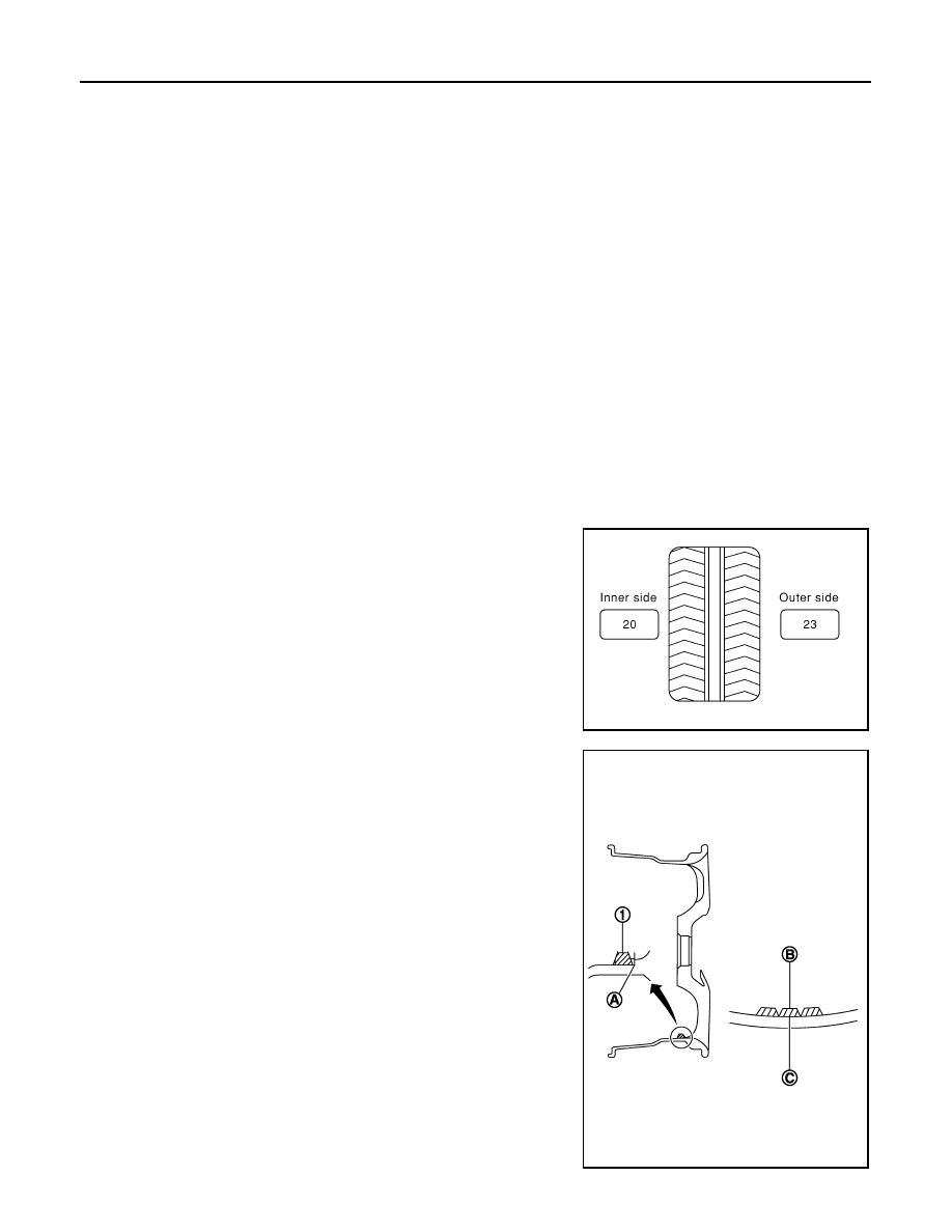
late the correct size adhesive weight to use. When inner and outer imbalance values are shown on the

balancer machine indicator, multiply outer imbalance value by 5/3 (1.67) to determine balance weight that

should be used. Select the outer balance weight with a value closest to the calculated value above and

install in to the designated outer position of, or at the designated angle in relation to the road wheel.

a. Indicated imbalance value 

× 5/3 = balance weight to be installed

Calculation example:

23 g (0.81 oz) 

× 5/3 (1.67) = 38.33 g (1.35 oz) ⇒ 40 g (1.41 oz)

balance weight (closer to calculated balance weight value)

NOTE:

Note that balance weight value must be closer to the calculated

balance weight value.

Example:

37.4 

⇒ 35 g (1.23 oz)

37.5 

⇒ 40 g (1.41 oz)

3. Install balance weight in the position shown.

CAUTION:

• Do not install the inner balance weight before installing

the outer balance weight.

• Before installing the balance weight, be sure to clean the

mating surface of the road wheel.

• When installing balance weight (1) to road wheel, set it into the

grooved area (A) on the inner wall of the road wheel as shown

so that the balance weight center (B) is aligned with the bal-

ancer machine indication position (angle) (C).

CAUTION:

• Always use Genuine NISSAN adhesive balance weights.

• Balance weights are non-reusable; always replace with

new ones.

• Do not install more than three sheets of balance weight.

SMA054D

JPEIC0040ZZ

WHEEL AND TIRE ASSEMBLY

WT-49

< PERIODIC MAINTENANCE >

C

D

F

G

H

I

J

K

L

M

A

B

WT

N

O

P

4. If calculated balance weight value exceeds 50 g (1.76 oz), install

two balance weight sheets in line with each other as shown.

CAUTION:

Do not install one balance weight sheet on top another.

5. Start balancer machine again.
6. Install balance weight on inner side of road wheel in the bal-

ancer machine indication position (angle).

CAUTION:

Do not install more than two balance weights.

7. Start balancer machine. Make sure that inner and outer residual

imbalance values are 5 g (0.17 oz) each or below.

8. If either residual imbalance value exceeds 5 g (0.17 oz), repeat installation procedures.

TIRE ROTATION

• Follow the maintenance schedule for tire rotation service intervals.

Refer to 

MA-6, "FOR USA AND CANADA : Explanation of General

Maintenance"

 (United States and Canada), or 

MA-8, "FOR MEX-

ICO : General Maintenance"

 (Mexico).

• When installing the wheel, tighten wheel nuts to the specified

torque.

CAUTION:

• Do not include the spare tire when rotating the tires.

• When installing wheels, tighten them diagonally by dividing

the work two to three times in order to prevent the wheels

from developing any distortion.

• Be careful not to tighten wheel nut at torque exceeding the

criteria for preventing strain of disc rotor.

• Use NISSAN genuine wheel nuts for aluminum wheels.

• Perform the ID registration, after tire rotation. Refer to 

WT-6, "Work Procedure"

.

Wheel balance

Dynamic (At flange)

Static (At flange)

Maximum allowable im-
balance

Refer to 

WT-53, "Road Wheel"

.

PEIA0033E

Wheel nut tightening 
torque

: 133 N·m (14 kg-m, 98 ft-lb)

SMA829C

WT-50

< UNIT REMOVAL AND INSTALLATION >

REMOVAL AND INSTALLATION

UNIT REMOVAL AND INSTALLATION

REMOVAL AND INSTALLATION

Exploded View

INFOID:0000000009480288

Transmitter (Pressure Sensor)

INFOID:0000000009480289

REMOVAL

1. Remove wheel and tire using power tool. Refer to 

WT-48, "Adjustment"

.

2. Remove valve cap and valve core to deflate the tire.

NOTE:

If the tire is to be reused, apply a matching mark on the tire in line with the position of the road wheel valve

stem assembly for the purpose of road wheel and tire balance adjustment after installation.

3. Remove the valve stem nut and allow transmitter to fall into tire.

4. Lubricate the tire outside bead well with a suitable non-silicone lubricant, and remove outside of tire from

the road wheel. Reach inside the tire and remove the transmitter.

CAUTION:

• Do not use silicone lubricant. Use of silicone lubricant will deteriorate the tire and road wheel.

• Be sure not to damage the road wheel or transmitter.

• Do not allow lubricant to make contact with transmitter.

5. Lubricate the tire inside bead well with a suitable non-silicone lubricant, and remove inside of tire from the

road wheel.

1.

Transmitter (tire pressure sensor)

2.

O-ring

3.

Valve stem nut

4.

Valve core

5.

Valve cap

6.

Valve stem assembly

:

Parts that are replaced as a set when the tire is replaced.

AWEIA0212GB

SEIA0047E

REMOVAL AND INSTALLATION

WT-51

< UNIT REMOVAL AND INSTALLATION >

C

D

F

G

H

I

J

K

L

M

A

B

WT

N

O

P

CAUTION:

• Do not use silicone lubricant. Use of silicone lubricant will deteriorate the tire and road wheel.

• Be sure not to damage the road wheel.

6. Remove the valve stem from the transmitter as shown.

INSTALLATION

1. Apply a suitable non-silicone lubricant to the tire inside bead.

CAUTION:

Do not use silicone lubricant. Use of silicone lubricant will deteriorate the tire and wheel.

2. Install the tire inside bead (1) onto the road wheel (2) in the posi-

tion shown.

3. Install the valve stem to the transmitter.
4. Install the O-ring to the transmitter.

CAUTION:

• Do not reuse O-ring.

• Insert O-ring to the base of the transmitter.

• The base of the valve stem (A) must be positioned in the

groove of the metal plate as shown.

JSEIA0378ZZ

JPEIC0105ZZ

JSEIA0376GB


Content   ..  1323  1324  1325  1326   ..