Content .. 1287 1288 1289 1290 ..
Nissan Frontier. Manual - part 1289
ASSEMBLY
TM-367
< UNIT DISASSEMBLY AND ASSEMBLY >
[5AT: RE5R05A]
C
E
F
G
H
I
J
K
L
M
A
B
TM
N
O
P
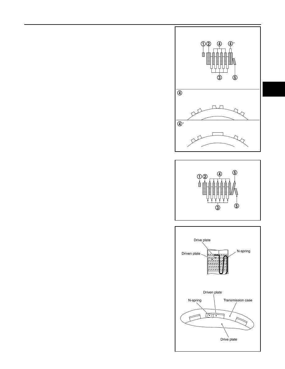
• QR25DE models
- Snap ring (1)
- Retaining plate (2)
- Drive plate (3)
- Driven plate (4)
- Dish plate (5)
- Drive plate/Driven plate:5/6
• VQ40DE models
- Snap ring (1)
- Retaining plate (2)
- Drive plate (3)
- Driven plate (4)
- Dish plate (5)
- Drive plate/Driven plate:6/6
19. Assemble N-spring.
20. Install reverse brake retaining plate in transmission case.
JSDIA2359ZZ
SCIA6949E
SCIA5249E