Nissan Frontier. Manual - part 1206


  Index      Nissan     Nissan Frontier (2014 year) - Service and Repair Manual


Search            


Content   ..  1204  1205  1206  1207   ..


Nissan Frontier. Manual - part 1206


SHIFT CONTROL COMPONENTS

TM-35

< UNIT DISASSEMBLY AND ASSEMBLY >

[FS5R30A]

C

E

F

G

H

I

J

K

L

M

A

B

TM

N

O

P

SHIFT CONTROL COMPONENTS

Disassembly

INFOID:0000000009480422

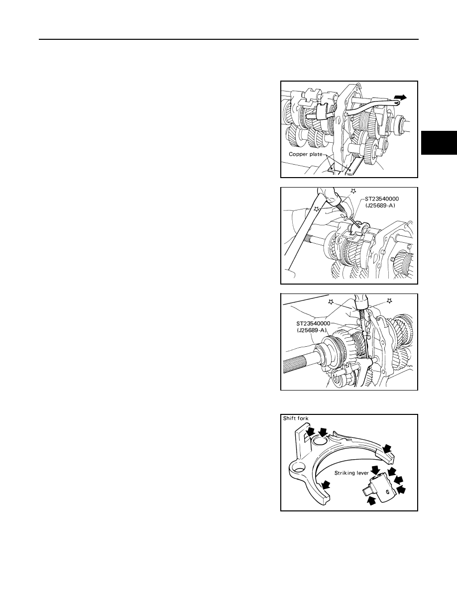
1. Mount adapter plate on vise using copper plates to protect

adapter plate.

2. Remove OD and reverse fork rod.

3. Drive out retaining pin from striking lever using Tool.

4. While pulling out striking rod, remove striking lever and striking

interlock. Then remove 1st and 2nd, 3rd and 4th, and reverse

shift forks.

5. Drive out retaining pin from OD shift fork using Tool.

6. Pull out OD fork rod and then remove OD shift fork.

Inspection

INFOID:0000000009480423

• Check contact surface and sliding surface for wear, scratches, pro-

jections or other damage.

SMT373A

Tool number

: ST23540000 (J-25689-A)

SMT374A

Tool number

: ST23540000 (J-25689-A)

SMT375A

SMT398A

TM-36

< UNIT DISASSEMBLY AND ASSEMBLY >

[FS5R30A]

SHIFT CONTROL COMPONENTS

Assembly

INFOID:0000000009480424

1. Install OD fork rod and OD shift fork. Then install new retaining

pin into OD shift fork.

CAUTION:

Do not reuse retaining pin.

2. Install 1st and 2nd, 3rd and 4th, and reverse shift forks onto coupling sleeve.
3. Install striking rod into hole of shift forks, striking lever and inter-

lock and then install new retaining pin into striking lever using

Tool.

CAUTION:

• Make sure that striking rod moves smoothly.

• Do not reuse retaining pin.

4. Apply sealant to thread of OD and reverse fork rod bolt, and

then install OD and reverse fork rod.

• Use Genuine Medium Strength Thread Locking Sealant or the equivalent. Refer to 

GI-21, "Rec-

ommended Chemical Products and Sealants"

.

SMT457A

Tool number

: ST23540000 (J-25689-A)

OD and reverse fork rod bolt Refer to 

TM-23, "Overhaul"

SMT374A

GEAR COMPONENTS

TM-37

< UNIT DISASSEMBLY AND ASSEMBLY >

[FS5R30A]

C

E

F

G

H

I

J

K

L

M

A

B

TM

N

O

P

GEAR COMPONENTS

Disassembly

INFOID:0000000009480425

1. Before removing gears and shafts, measure each gear end play.

Refer to 

TM-54, "Gear End Play"

.

• If not within specification, disassemble and check contact sur-

face of gear to hub, washer, bushing, needle bearing and

shaft.

2. Remove rear side components on mainshaft and counter gear.
a. Remove reverse coupling sleeve.

b. Remove mainshaft rear snap ring and counter gear rear snap

ring using suitable tool.

c. Remove C-ring holder and mainshaft C-rings from mainshaft

using suitable tool. 

d. Remove counter gear rear end bearing using suitable tool.
e. Remove reverse idler thrust washer, reverse idler gear and

reverse idler needle bearings.

f.

Remove mainshaft rear bearing using Tools.

SMT376A

SMT463A

SMT377A

Tool number

 (J-26349-A)

: —


(J-25726-B)

SMT378A

TM-38

< UNIT DISASSEMBLY AND ASSEMBLY >

[FS5R30A]

GEAR COMPONENTS

g. Remove reverse main gear together with mainshaft spacer and

reverse synchronizer hub using suitable tool. Then remove

reverse gear needle bearings.

h. Remove reverse counter gear using suitable tool.
i.

Remove OD coupling sleeve together with OD baulk ring,

reverse baulk ring and spring inserts.

j.

Remove reverse gear bushing using suitable tool.

k.

Remove OD counter gear and reverse cone using suitable tool.

l.

Remove OD gear needle bearing.

m. Remove reverse idler shaft.

3. Press out mainshaft, OD main gear, OD gear bushing and counter gear alternately using Tool.

SMT380A

SMT773A

SMT770A

SMT771A

Tool number

: ST33230000 ( — )


Content   ..  1204  1205  1206  1207   ..