Content .. 1182 1183 1184 1185 ..
Nissan Frontier. Manual - part 1184
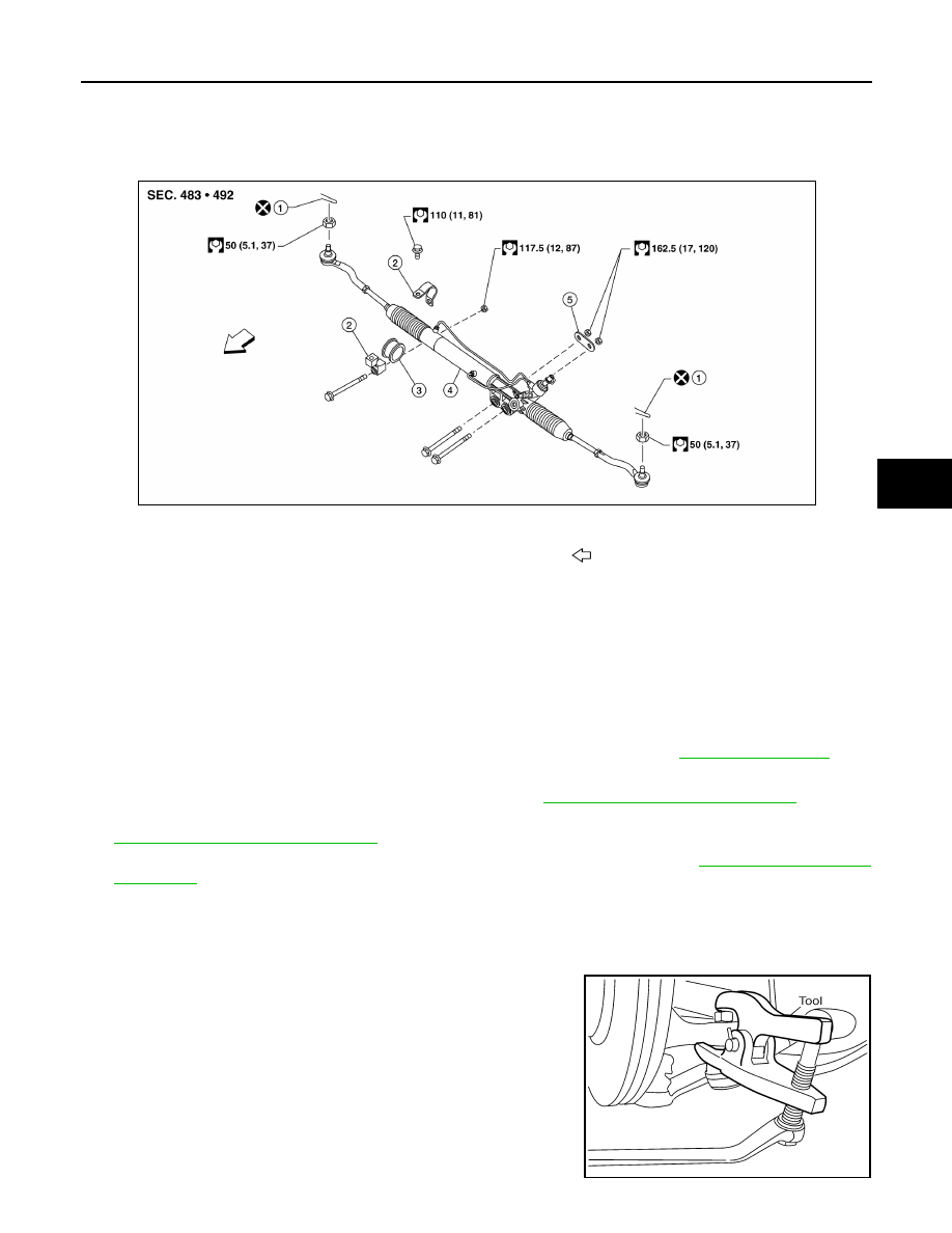
POWER STEERING GEAR AND LINKAGE
ST-15
< REMOVAL AND INSTALLATION >
C
D
E
F
H
I
J
K
L
M
A
B
ST
N
O
P
POWER STEERING GEAR AND LINKAGE
Removal and Installation
INFOID:0000000009479922
CAUTION:
Spiral cable may snap due to steering operation if the steering column is separated from the steering
gear assembly. Therefore secure the steering wheel to avoid turning.
NOTE:
When removing components such as hoses, tubes/lines, etc., cap or plug openings to prevent fluid from spill-
ing.
REMOVAL
1. Set front wheels in the straight-ahead position.
2. Remove the front wheels and tires from the vehicle, using power tool. Refer to
.
3. Drain the power steering fluid.
4. Remove the engine under cover, using power tool. Refer to
EXT-15, "Removal and Installation"
.
5. On 4WD models, remove the front final drive, then support the drive shafts, using suitable wire. Refer to
DLN-191, "Removal and Installation"
.
6. Remove the stabilizer bar brackets and reposition the stabilizer bar. Refer to
.
7. Remove the cotter pins at the steering outer sockets.
CAUTION:
Do not reuse the cotter pins.
8. Loosen the outer socket nuts.
9. Remove the steering outer sockets from the steering knuckles,
using Tool, then remove the nuts.
CAUTION:
• Do not damage the outer socket boots.
• Do not damage the outer socket threads. Thread the ball
joint nut onto the end of the outer socket during removal.
1.
Cotter pin
2.
Bracket
3.
Insulator
4.
Steering gear assembly
5.
Washer
Front
AWGIA0253ZZ
Tool number
: HT72520000 (J-25730-A)
WGIA0130E