Nissan Frontier. Manual - part 1149


  Index      Nissan     Nissan Frontier (2014 year) - Service and Repair Manual


Search            


Content   ..  1147  1148  1149  1150   ..


Nissan Frontier. Manual - part 1149


SN

SONAR SYSTEM OFF SWITCH CIRCUIT INSPECTION

SN-13

< DTC/CIRCUIT DIAGNOSIS >

C

D

E

F

G

H

I

J

K

L

M

B

A

O

P

Component Inspection

INFOID:0000000009480112

1.

SONAR SYSTEM OFF SWITCH

1. Turn ignition switch OFF.

2. Disconnect sonar system OFF switch connector.

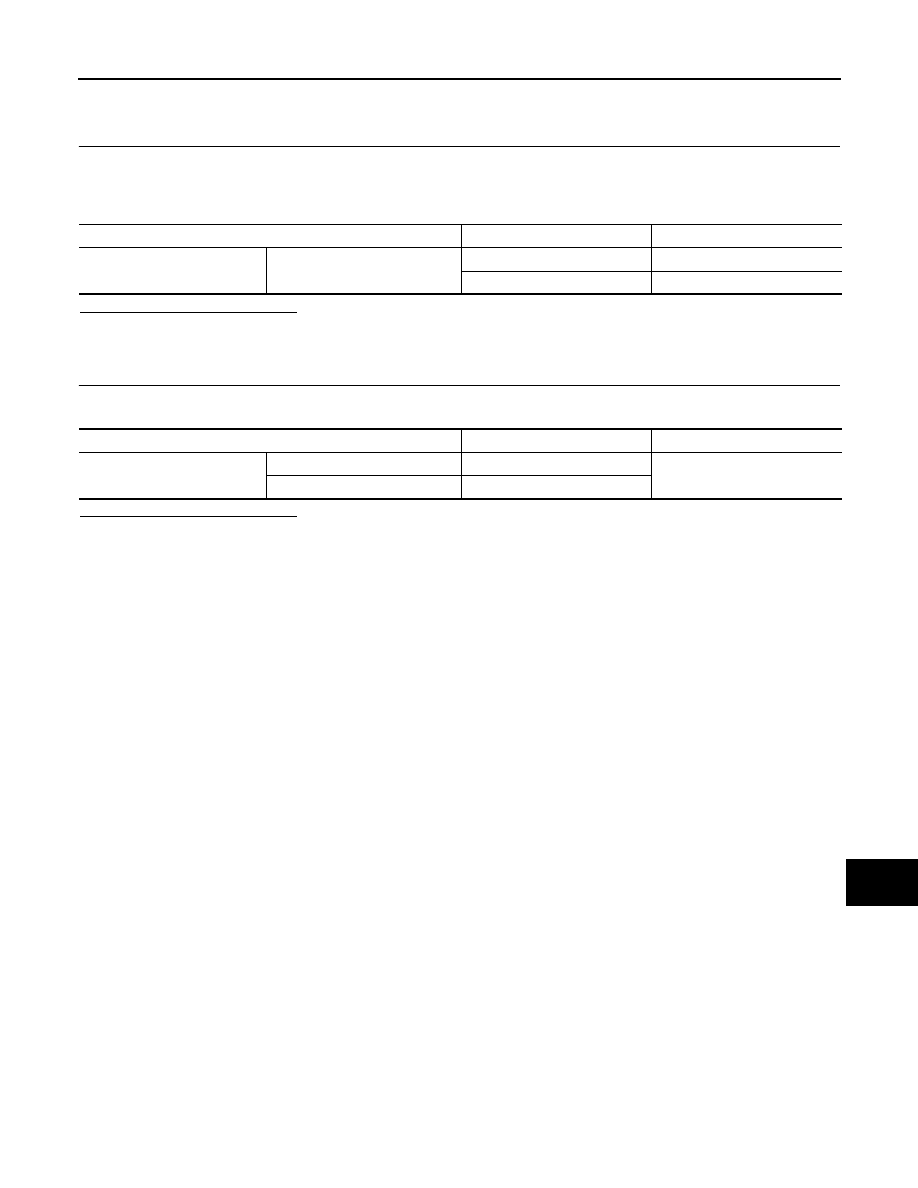
3. Check continuity between sonar system OFF switch terminals.

Is the inspection result normal?

YES

>> GO TO 2.

NO

>> Replace sonar system OFF switch.

2.

SONAR SYSTEM OFF INDICATOR

Apply battery voltage to terminal 5 and ground to terminal 6 of sonar system OFF switch.

Is the inspection result normal?

YES

>> Inspection End.

NO

>> Replace sonar system OFF switch.

Sonar system OFF switch terminals

Condition

Continuity

1

2

Switch pressed

Yes

Switch released

No

Sonar system OFF switch

Condition

Result

Terminal

5

Battery voltage applied

Indicator ON

6

Ground applied

SN-14

< ECU DIAGNOSIS INFORMATION >

SONAR CONTROL UNIT

ECU DIAGNOSIS INFORMATION

SONAR CONTROL UNIT

Reference Value

INFOID:0000000009480113

SONAR CONTROL UNIT TERMINAL LAYOUT

TERMINALS AND REFERENCE VALUES FOR SONAR CONTROL UNIT

WKIA5222E

Terminal

(wire color)

Description

Condition

Reference value

(Approx.)

+

Signal name

Input/

Output

Ignition 

switch

Operation

3

(R)

Ground

Rear sonar buzzer return 
signal

Input

ON

Obstacle detected

0 – 12 V (variable)

4

(V)

Ground

Sonar system OFF indica-
tor signal

Output

ON

Sonar system OFF switch 
ON

0 V

Sonar system OFF switch 
OFF

Battery voltage

5

(SB)

Ground Reverse signal

Input

ON

Selector lever in R (re-
verse) position

Battery voltage

Selector lever in any posi-
tion except R (reverse)

0 V

6

(B)

Ground Sonar control unit ground 

Input

OFF

0 V

7

(L)

Ground

Rear sonar buzzer drive 
signal

Output

ON

Obstacle detected

Battery voltage

8

(W/G)

Ground Sonar control unit power

Input

ON

Battery voltage

9

(GR)

Ground RH outer sensor signal

Input

ON

Selector lever in R (re-
verse) position

10

(P)

Ground LH outer sensor signal

Input

ON

Selector lever in R (re-
verse) position

SKIB8942E

SKIB8942E

SN

SONAR CONTROL UNIT

SN-15

< ECU DIAGNOSIS INFORMATION >

C

D

E

F

G

H

I

J

K

L

M

B

A

O

P

DTC Index

INFOID:0000000009480114

11

(BG)

Ground LH inner sensor signal

Input

ON

Selector lever in R (re-
verse) position

12

(LG)

Ground RH inner sensor signal

Input

ON

Selector lever in R (re-
verse) position

13

(G)

Ground

Sonar system OFF switch 
ON/OFF signal

Output

ON

Sonar system OFF switch 
ON

0 V

Sonar system OFF switch 
OFF

Battery voltage

15

(Y)

Ground Rear sensor ground

Output

ON

0 V

16

(W)

Ground Rear sensor power

Output

ON

Battery voltage

Terminal

(wire color)

Description

Condition

Reference value

(Approx.)

+

Signal name

Input/

Output

Ignition 

switch

Operation

SKIB8942E

SKIB8942E

Fault Code

Malfunction

Service Procedure

11

Rear sonar sensor LH outer

1.

Check harness for open or short.

2.

Replace sonar sensor.  Refer to 

SN-25, "Removal and In-

stallation"

.

12

Rear sonar sensor LH inner

13

Rear sonar sensor RH inner

14

Rear sonar sensor RH outer

21

Rear sonar buzzer

1.

Refer to 

SN-11, "Diagnosis Procedure"

.

2.

Check harness for open or short.

3.

Refer to 

SN-22, "Symptom Table"

.

22

Sonar system OFF indicator

1.

Refer to 

SN-12, "Diagnosis Procedure"

.

2.

Check harness for open or short.

3.

Refer to symptom table.

23

Sonar system OFF switch

24

Sonar control unit

Replace sonar control unit. Refer to 

SN-26, "Removal and In-

stallation"

.

SN-16

< WIRING DIAGRAM >

SONAR SYSTEM

WIRING DIAGRAM

SONAR SYSTEM

Wiring Diagram

INFOID:0000000009480115

ABNWA2063GB


Content   ..  1147  1148  1149  1150   ..