Content .. 1090 1091 1092 1093 ..
Nissan Frontier. Manual - part 1092
AXLE SHAFT
RAX-19
< SERVICE INFORMATION >
[M226]
C
E
F
G
H
I
J
K
L
M
A
B
RAX
N
O
P
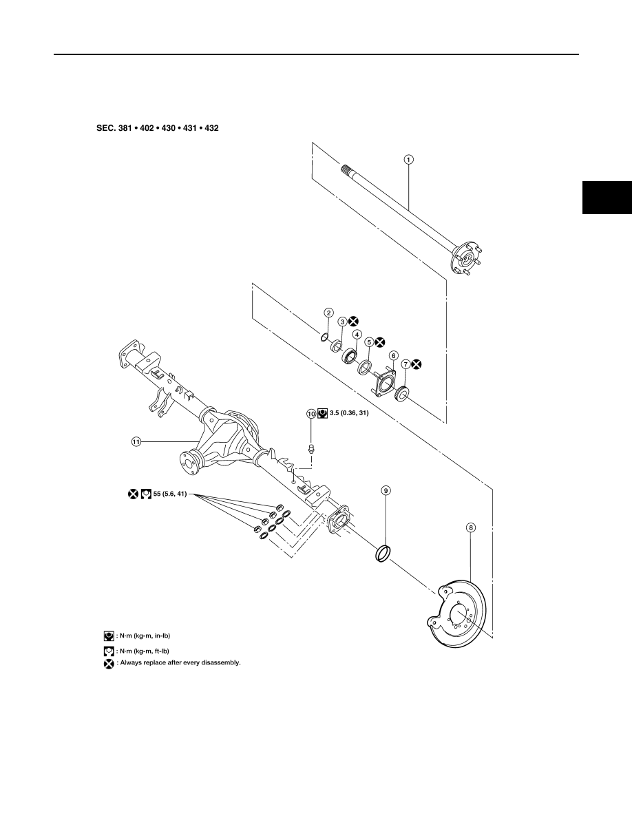
AXLE SHAFT
Removal and Installation
INFOID:0000000009478721
CAUTION:
1.
Axle shaft
2.
Snap ring
3.
Bearing ring retainer
4.
Axle shaft bearing
5.
Axle oil seal
6.
Axle shaft bearing cage
7.
Wheel sensor rotor
8.
Back plate and torque member
9.
Axle shaft bearing cup
10. Breather
11. Rear final drive
WDIA0181E