Nissan Frontier. Manual - part 95
BCS
COMBINATION SWITCH READING SYSTEM
BCS-9
< SYSTEM DESCRIPTION >
C
D
E
F
G
H
I
J
K
L
B
A
O
P
N
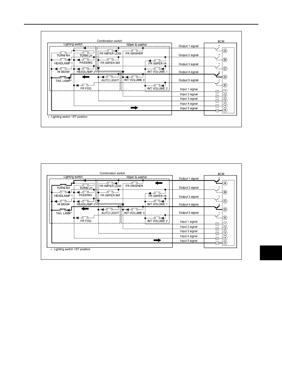
• The circuit between OUTPUT 4 and INPUT 5 is formed when the TAIL LAMP switch is turned ON.
• BCM detects the combination switch status signal “5D” when the signal of OUTPUT 4 is input to INPUT 5.
• BCM judges that the TAIL LAMP switch is ON when the signal “5D” is detected.
Example 2: When some switches (TURN RH, TAIL LAMP) are turned ON
• The circuits between OUTPUT 1 and INPUT 5 and between OUTPUT 4 and INPUT 5 are formed when the
TURN RH switch and TAIL LAMP switch are turned ON.
• BCM detects the combination switch status signal “5AD” when the signals of OUTPUT 1 and OUTPUT 4 are
input to INPUT 5.
• BCM judges that the TURN RH switch and TAIL LAMP switch are ON when the signal “5AD” is detected.
WIPER INTERMITTENT DIAL POSITION SETTING (FRONT WIPER INTERMITTENT OPERATION)
BCM judges the wiper intermittent dial 1 - 7 by the status of INT VOLUME 1, 2, and 3 switches.
AWMIA1245GB
AWMIA1246GB