Nissan Frontier. Manual - part 82
AV-320
< DTC/CIRCUIT DIAGNOSIS >
[NAVIGATION]
SUBWOOFER
Is the inspection result normal?
YES
>> Replace subwoofer. Refer to
AV-354, "Removal and Installation"
NO
>> GO TO 4.
4.
CHECK PRE-AMP SIGNAL CIRCUIT CONTINUITY
1. Disconnect AV control unit connector M96 and audio amplifier connector B159.
2. Check continuity between AV control unit connector M96 and audio amplifier connector B159.
3. Check continuity between AV control unit connector M96 and ground.
Is the inspection result normal?
YES
>> GO TO 5.
NO
>> Repair or replace harness or connectors.
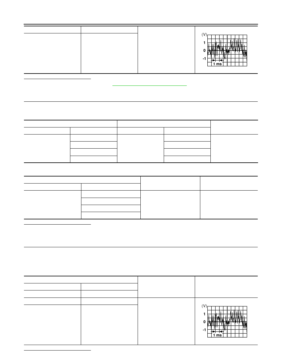
5.
CHECK PRE-AMP SIGNAL
1. Connect AV control unit connector M96 and audio amplifier connector B159.
2. Turn ignition switch to ACC.
3. Push AV control unit POWER switch.
4. Check signal between the terminals of AV control unit connector M96.
Is the inspection result normal?
2
18
Audio signal output
3
19
SKIA0177E
AV control unit
Audio amplifier
Continuity
Connector
Terminal
Connector
Terminal
M96
4
B159
24
Yes
5
8
13
23
14
7
AV control unit
Ground
Continuity
Connector
Terminal
M96
4
—
No
5
13
14
AV control unit connector M96
Condition
Reference value
(+)
(
−)
Terminal
Terminal
4
5
Audio signal output
13
14
SKIA0177E