Nissan Frontier. Manual - part 35


  Index      Nissan     Nissan Frontier (2014 year) - Service and Repair Manual


Search            


Content   ..  33  34  35  36   ..


Nissan Frontier. Manual - part 35


AV-132

< DTC/CIRCUIT DIAGNOSIS >

[DISPLAY AUDIO WITHOUT AMPLIFIER]

REAR VIEW CAMERA IMAGE SIGNAL CIRCUIT

2. Disconnect audio unit connector M45 and rear view camera connector.

3. Check continuity between audio unit connector M45 and rear view camera connector C251.

4. Check continuity between audio unit connector M45 and ground.

Is the inspection result normal?

YES

>> GO TO 5.

NO

>> Repair or replace harness or connectors.

5.

CHECK CAMERA GROUND CIRCUIT CONTINUITY

Check continuity between audio unit connector M45 and rear view camera connector C251.

Is the inspection result normal?

YES

>> GO TO 6.

NO

>> Repair or replace harness or connectors.

6.

CHECK CAMERA IMAGE SIGNAL

1. Connect audio unit connector M45 and rear view camera connector.

2. Turn ignition switch ON.

3. Shift the selector lever to R (reverse).

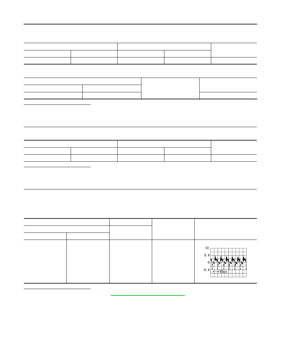
4. Check signal between audio unit connector M45 and ground.

Is the inspection result normal?

YES

>> Replace audio unit. Refer to 

AV-146, "Removal and Installation"

.

NO

>> Replace rear view camera.

Audio unit

Rear view camera

Continuity

Connector

Terminal

Connector

Terminal

M45

35

C251

3

Yes

Audio unit

Ground

Continuity

Connector

Terminal

M45

35

No

Audio unit

Rear view camera

Continuity

Connector

Terminal

Connector

Terminal

M45

36

C251

6

Yes

Audio unit

Ground

Condition

Reference value

(+)

(

−)

Connector

Terminal

M45

35

Camera image dis-

played.

SKIB2251J

AV

STEERING SWITCH

AV-133

< DTC/CIRCUIT DIAGNOSIS >

[DISPLAY AUDIO WITHOUT AMPLIFIER]

C

D

E

F

G

H

I

J

K

L

M

B

A

O

P

STEERING SWITCH

Diagnosis Procedure

INFOID:0000000009482116

Regarding Wiring Diagram information, refer to 

AV-104, "Wiring Diagram"

.

1.

CHECK STEERING WHEEL AUDIO CONTROL SWITCH RESISTANCE

1. Disconnect combination switch connector M102.

2. Check resistance between combination switch connector terminals.

Is the inspection result normal?

YES

>> GO TO 2.

NO

>> Replace steering wheel audio control switches. Refer to 

AV-150, "Removal and Installation"

.

2.

CHECK HARNESS BETWEEN BLUETOOTH

®

 CONTROL UNIT AND COMBINATION SWITCH

1. Turn ignition switch OFF.
2. Disconnect Bluetooth

®

 control unit connector B141 and combination switch connector M30.

3. Check continuity between Bluetooth

®

 control unit connector B141 and combination switch connector M30.

4. Check continuity between Bluetooth

®

 control unit connector B141 and ground.

Is the inspection result normal?

YES

>> GO TO 3.

NO

>> Repair or replace harness or connectors.

3.

SPIRAL CABLE CHECK

Check continuity between combination switch connectors M30 and M102.

Combination switch connector M102

Condition

Resistance (

Ω)

(Approx.)

Terminal

Terminal

16

18

Depress VOL DOWN switch.

1

Depress VOL UP switch.

121

Depress  

switch.

321

15

Depress MODE switch.

1

Depress  

switch.

121

Depress  

switch.

321

Depress  

switch.

723

Bluetooth

®

 control unit

Combination switch

Continuity

Connector

Terminal

Connector

Terminal

B141

12

M30

24

Yes

13

25

14

31

Bluetooth

®

 control unit

Continuity

Connector

Terminal

B141

12

Ground

No

13

14

AV-134

< DTC/CIRCUIT DIAGNOSIS >

[DISPLAY AUDIO WITHOUT AMPLIFIER]

STEERING SWITCH

Is the inspection result normal?

YES

>> GO TO 4.

NO

>> Replace spiral cable. Refer to 

SR-13, "Removal and Installation"

.

4.

CHECK HARNESS BETWEEN BLUETOOTH

®

 CONTROL UNIT AND AUDIO UNIT

1. Disconnect audio unit connector M44.
2. Check continuity between Bluetooth

®

 control unit connector B141 and audio unit connector M44.

3. Check continuity between Bluetooth

®

 control unit connector B141 and ground.

Is the inspection result normal?

YES

>> Replace audio unit. Refer to 

AV-146, "Removal and Installation"

.

NO

>> Repair or replace harness or connectors.

Combination switch

Continuity

Connector

Terminal

Connector

Terminal

M30

24

M102

15

Yes

25

16

31

18

Bluetooth

®

 control unit

Audio unit

Continuity

Connector

Terminal

Connector

Terminal

B141

17

M44

6

Yes

18

16

19

15

Bluetooth

®

 control unit

Continuity

Connector

Terminal

B141

17

Ground

No

18

19

AV

MICROPHONE SIGNAL CIRCUIT

AV-135

< DTC/CIRCUIT DIAGNOSIS >

[DISPLAY AUDIO WITHOUT AMPLIFIER]

C

D

E

F

G

H

I

J

K

L

M

B

A

O

P

MICROPHONE SIGNAL CIRCUIT

Diagnosis Procedure

INFOID:0000000009482117

Regarding Wiring Diagram information, refer to 

AV-104, "Wiring Diagram"

.

1.

CHECK HARNESS BETWEEN BLUETOOTH

®

 CONTROL UNIT AND MICROPHONE

1. Turn ignition switch OFF.
2. Disconnect Bluetooth

®

 control unit connector B141 and microphone connector.

3. Check continuity between Bluetooth

®

 control unit connector B141 and microphone connector R8.

4. Check continuity between Bluetooth

®

 control unit connector B141 and ground.

Is the inspection result normal?

YES

>> GO TO 2.

NO

>> Repair harness or connector.

2.

CHECK MICROPHONE POWER SUPPLY

1. Connect Bluetooth

®

 control unit connector B141 and microphone connector.

2. Turn ignition switch ON.

3. Check voltage between microphone connector R8 terminal 4 and ground.

Is the inspection result normal?

YES

>> GO TO 3.

NO

>> Replace Bluetooth

®

 control unit. Refer to 

AV-151, "Removal and Installation"

.

3.

CHECK MICROPHONE SIGNAL

Check signal between Bluetooth

®

 control unit connector B141 with CONSULT or and oscilloscope.

Bluetooth

®

 control unit

Microphone

Continuity

Connector

Terminal

Connector

Terminal

B141

7

R8

1

Yes

8

2

29

4

Bluetooth

®

 control unit

Continuity

Connector

Terminal

B141

7

Ground

No

8

29

Microphone

Ground

Value (Approx.)

Connector

Terminal

R8

4

5V


Content   ..  33  34  35  36   ..