Nissan Frontier. Manual - part 32
AV-120
< BASIC INSPECTION >
[DISPLAY AUDIO WITHOUT AMPLIFIER]
DIAGNOSIS AND REPAIR WORKFLOW
BASIC INSPECTION
DIAGNOSIS AND REPAIR WORKFLOW
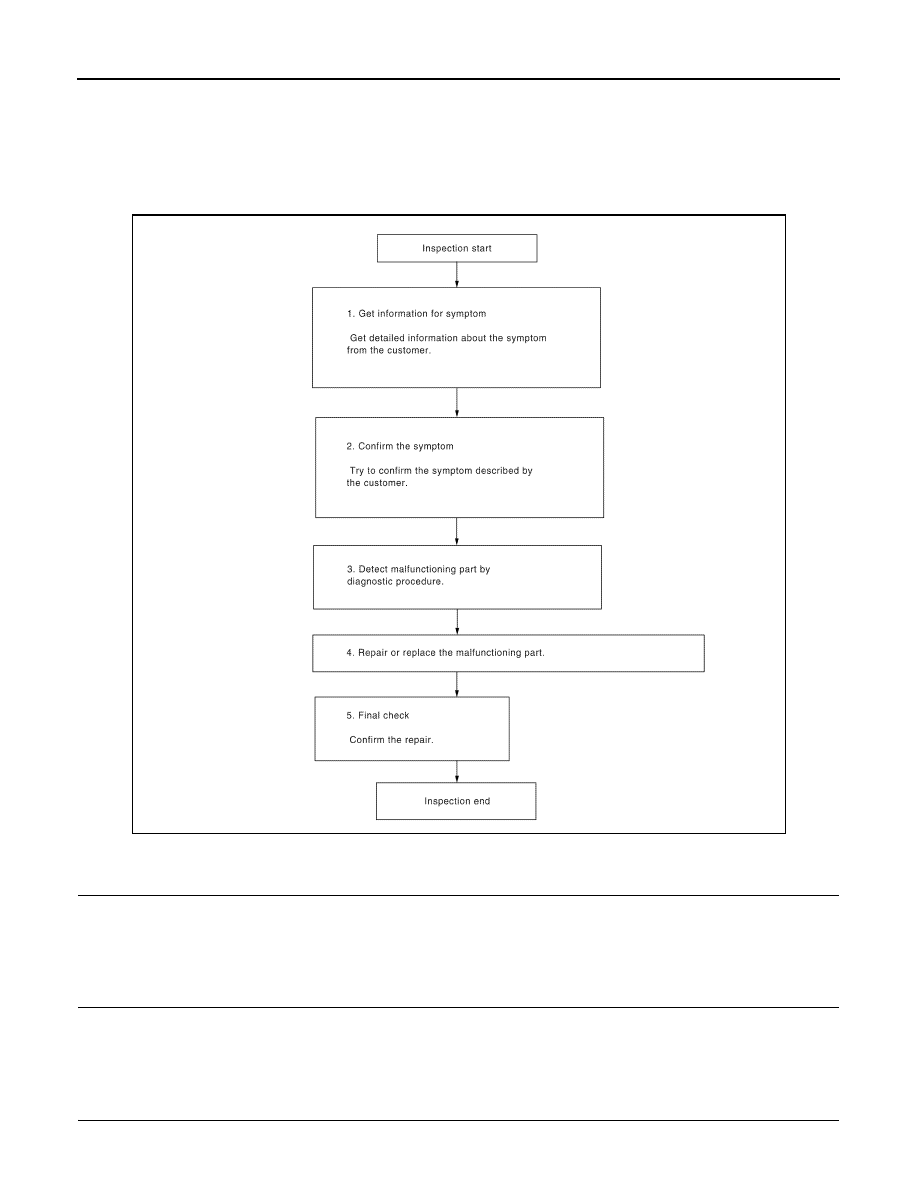
Work Flow
INFOID:0000000009482108
OVERALL SEQUENCE
DETAILED FLOW
1.
GET INFORMATION FOR SYMPTOM
Get detailed information from the customer about the symptom (the condition and the environment when the
incident/malfunction occurred).
>> GO TO 2.
2.
CONFIRM THE SYMPTOM
Try to confirm the symptom described by the customer. Verify relation between the symptom and the condition
when the symptom is detected.
>> GO TO 3.
3.
DETECT MALFUNCTIONING PART BY DIAGNOSTIC PROCEDURE
Inspect according to Diagnostic Procedure of the system.
ALNIA0182GB