Nissan Sentra. Manual - part 940
WW-8
< SYSTEM DESCRIPTION >
SYSTEM
SYSTEM
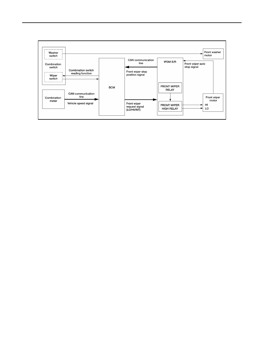
System Diagram
INFOID:0000000009756070
System Description
INFOID:0000000009756071
FRONT WIPER CONTROL (BASIC)
1. BCM detects the combination switch position by the combination switch reading function.
2. BCM transmits the front wiper request signal to the IPDM E/R using CAN communication.
3. IPDM E/R controls the integrated front wiper relay and front wiper high relay based on the status of the
front wiper request signal.
4. IPDM E/R provides power to operate the front wiper motor.
LOW SPEED OPERATION
1. Ignition switch ON.
2. Front wiper switch in LO or MIST position.
3. BCM reads the combination switch position and transmits the front wiper request signal (LO) to IPDM E/R
using CAN communication.
4. IPDM E/R turns ON the front wiper relay.
HIGH SPEED OPERATION
1. Ignition switch ON.
2. Front wiper switch in HI.
3. BCM reads the combination switch position and transmits the front wiper request signal (HI) to IPDM E/R
using CAN communication.
4. IPDM E/R turns ON the front wiper relay and the front wiper high relay.
INTERMITTENT OPERATION
1. Ignition switch ON.
2. Front wiper switch INT.
3. BCM reads the combination switch position. BCM calculates the delay interval based on the table below
and then transmits the front wiper request signal (INT) to IPDM E/R using CAN communication.
4. IPDM E/R turns ON the front wiper relay only once.
5. BCM detects stop position of the front wiper motor based on the front wiper stop position signal received
from the IPDM E/R.
6. BCM transmits the front wiper request signal (INT) again after the delay interval.
ABLIA2794GB