Nissan Sentra. Manual - part 882
TM-164
< DTC/CIRCUIT DIAGNOSIS >
[CVT: RE0F11A]
P0705 TRANSMISSION RANGE SENSOR A
6.
CHECK R POSITION SW CIRCUIT (PART1)
1. Turn ignition switch OFF.
2. Disconnect TCM connector.
3. Check continuity between TCM harness connector terminals.
Is the check result normal?
YES
>> GO TO 7.
NO
>> Repair or replace malfunctioning parts.
7.
CHECK R POSITION SW CIRCUIT (PART 2)
1. Disconnect transmission range switch connector.
2. Turn ignition switch ON.
3. Check voltage between TCM harness connector terminal and ground.
Is the check result normal?
YES
>> GO TO 12.
NO
>> Repair or replace malfunctioning parts.
8.
CHECK P POSITION SW CIRCUIT (PART 1)
1. Turn ignition switch OFF.
2. Disconnect TCM connector.
3. Check continuity between TCM harness connector terminals.
Is the check result normal?
YES
>> GO TO 9.
NO
>> Repair or replace malfunctioning parts.
9.
CHECK P POSITION SW CIRCUIT (PART 2)
1. Disconnect transmission range switch connector.
2. Turn ignition switch ON.
3. Check voltage between TCM harness connector terminal and ground.
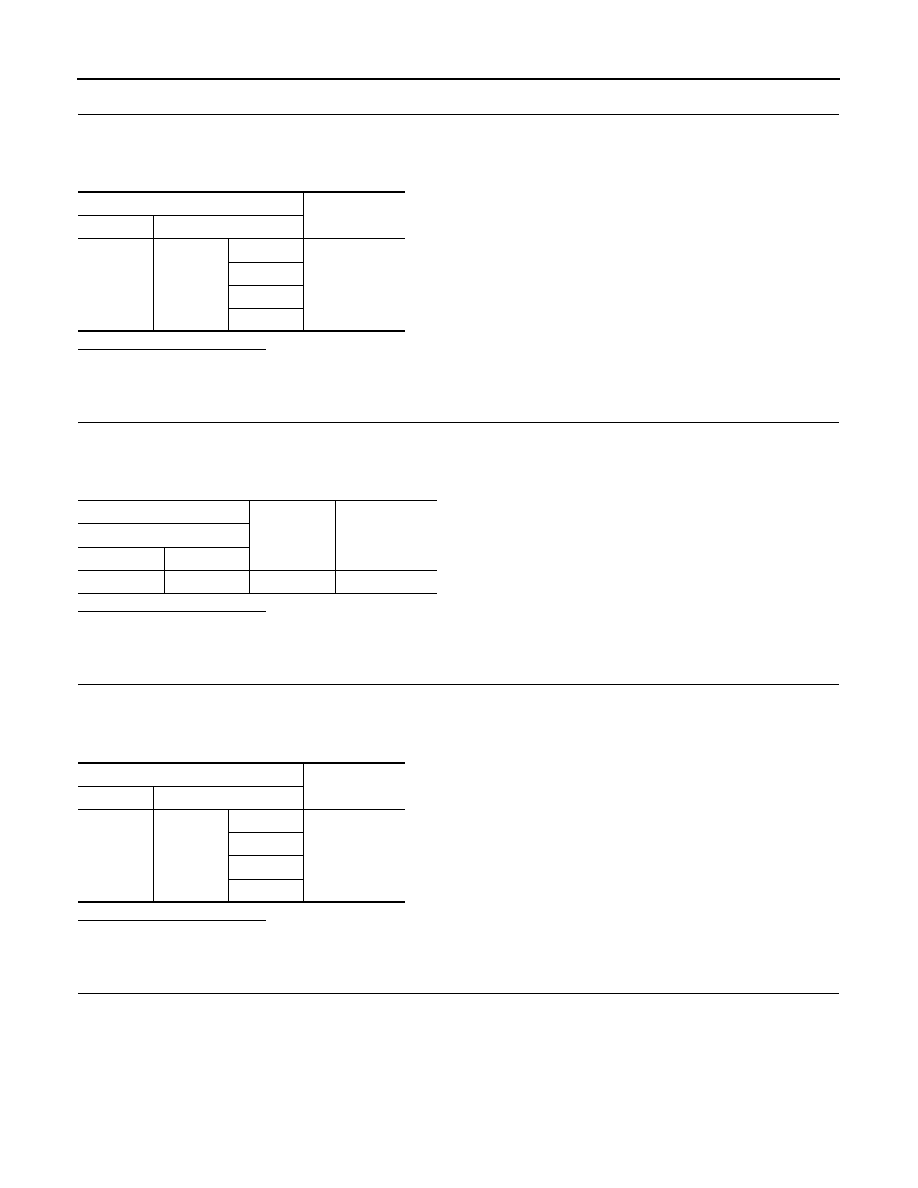
TCM
Continuity
Connector
Terminal
F23
6
2
Not existed
4
5
7
+
-
Voltage
(Approx.)
TCM
Connector
Terminal
F23
6
Ground
0 V
TCM
Continuity
Connector
Terminal
F23
7
2
Not existed
4
5
6