Nissan Sentra. Manual - part 840
STR-28
< DTC/CIRCUIT DIAGNOSIS >
S CONNECTOR CIRCUIT
S CONNECTOR CIRCUIT
Description
INFOID:0000000009759165
The starter motor magnetic switch is supplied with power when the ignition switch is turned to the START posi-
tion while the selector lever is in the P (Park) or N (Neutral) position (CVT Models) or the clutch pedal is
depressed (M/T Models).
Diagnosis Procedure
INFOID:0000000009759166
Regarding Wiring Diagram information, refer to
(with Intellignet Key system) or
(without Intelligent Key system).
CAUTION:
Perform diagnosis under the condition that engine cannot start by the following procedure.
1. Remove fuel pump fuse.
2. Crank or start the engine (where possible) until the fuel pressure is released.
1.
CHECK “S” CONNECTOR CIRCUIT
1. Turn ignition switch OFF.
2. Disconnect starter motor connector.
3. Shift selector lever to “P” (Park) or “N” (Neutral) position (CVT Models) or the clutch pedal is depressed
(M/T Models).
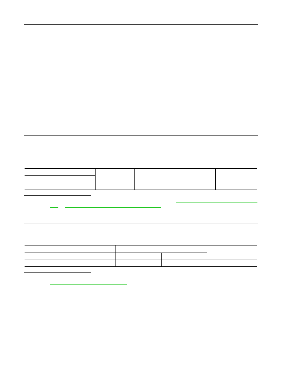
4. Check voltage between starter motor harness connector F28 and ground.
Is the inspection result normal?
YES
>> “S” circuit is OK. Further inspection is necessary. Refer to
STR-20, "Work Flow (With GR8-1200
STR-24, "Work Flow (Without GR8-1200 NI)"
.
NO
>> GO TO 2.
2.
CHECK HARNESS CONTINUITY (OPEN CIRCUIT)
1. Disconnect IPDM E/R connector.
2. Check continuity between starter motor harness connector F28 and the IPDM E/R harness connector
E44.
Is the inspection result normal?
YES
>> Further inspection is necessary. Refer to
STR-20, "Work Flow (With GR8-1200 NI)"
"Work Flow (Without GR8-1200 NI)"
.
NO
>> Repair or replace the harness or connectors.
(+)
(-)
Condition
Voltage
(Approx.)
Connector Terminal
F28
ST
Ground
When the ignition switch is in START position
Battery voltage
Starter motor harness connector
IPDM E/R harness connector
Continuity
Connector
Terminal
Connector
Terminal
F28
ST
E44
19
Yes