Nissan Sentra. Manual - part 821
ST-10
< REMOVAL AND INSTALLATION >
STEERING WHEEL
REMOVAL AND INSTALLATION
STEERING WHEEL
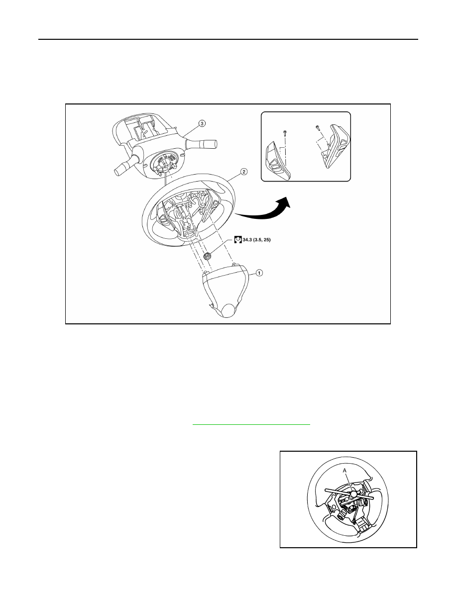
Exploded View
INFOID:0000000009759136
Removal and Installation
INFOID:0000000009759137
REMOVAL
NOTE:
When reconnecting spiral cable, fix cable with a tape so that fixing case and rotating part keep aligned. This
will omit neutral position alignment procedure during spiral cable installation.
1. Set steering wheel to the straight-ahead position.
2. Remove driver air bag module. Refer to
SR-12, "Removal and Installation"
.
3. Disconnect harness connectors from clipping locations.
4. Remove steering wheel lock nut.
5. Remove steering wheel using suitable tool (A).
NOTE:
Put paint marks on the steering wheel and the column shaft
head for supporting accurate positioning during the installation
procedure.
INSTALLATION
1.
Driver air bag module
2.
Steering wheel
3.
Steering column assembly
ALGIA0150ZZ
SGIA1524J