Nissan Sentra. Manual - part 764
SEC-84
< DTC/CIRCUIT DIAGNOSIS >
[WITH INTELLIGENT KEY SYSTEM]
B2602 SHIFT POSITION
Is the inspection result normal?
YES
>> GO TO 8.
NO
>> Replace CVT shift selector. Refer to
TM-253, "Removal and Installation"
8.
CHECK INTERMITTENT INCIDENT
GI-39, "Intermittent Incident"
>> Inspection End.
Component Inspection
INFOID:0000000009756729
1.
CHECK CVT SHIFT SELECTOR (PARK POSITION SWITCH)
1. Turn ignition switch OFF.
2. Disconnect CVT shift selector connector.
3. Check continuity between CVT shift selector (park position switch) terminals.
Is the inspection result normal?
YES
>> Inspection End.
NO
>> Replace CVT shift selector. Refer to
TM-253, "Removal and Installation"
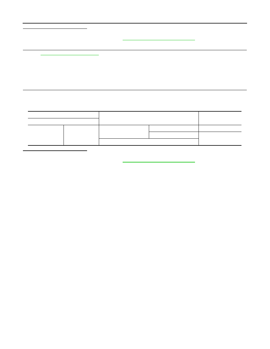
CVT shift selector (park position switch)
Condition
Continuity
Terminal
12
13
Selector lever: P position
Selector button: Released
No
Selector button: Pressed
Yes
Selector lever: Other than P position