Nissan Sentra. Manual - part 761


  Index      Nissan     Nissan Sentra (2014 year) - Service and Repair Manual


Search            


Content   ..  759  760  761  762   ..


Nissan Sentra. Manual - part 761


SEC-72

< DTC/CIRCUIT DIAGNOSIS >

[WITH INTELLIGENT KEY SYSTEM]

B2198 NATS ANTENNA AMP.

Is the inspection result normal?

YES

>> Replace IPDM E/R. Refer to 

PCS-30, "Removal and Installation"

.

NO

>> Repair or replace harness.

4.

CHECK NATS ANTENNA AMP. GROUND CIRCUIT

Check continuity between NATS antenna amp. harness connector and ground.

Is the inspection result normal?

YES

>> GO TO 5.

NO

>> Repair or replace harness.

5.

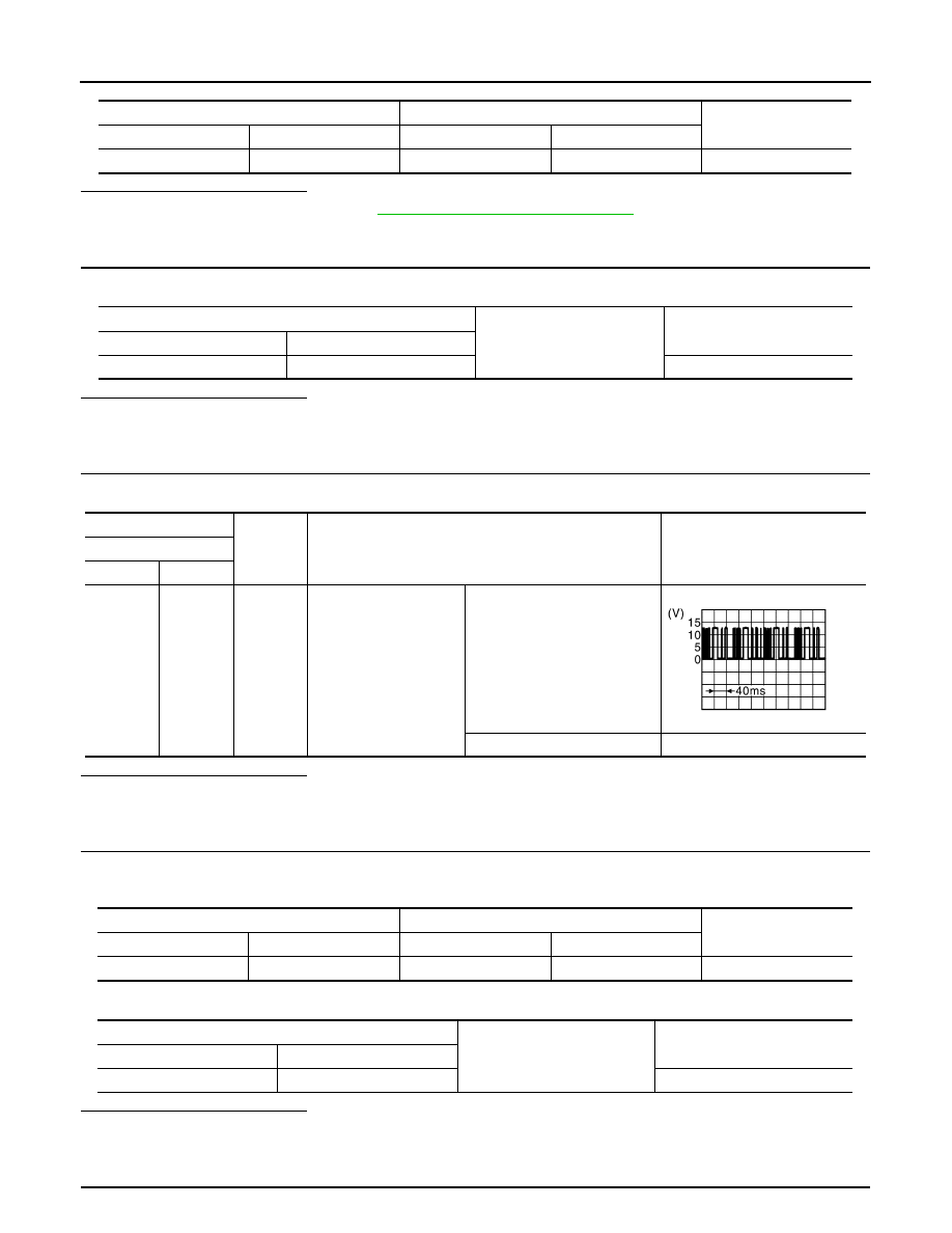
CHECK NATS ANTENNA AMP. COMMUNICATION SIGNAL 1

Check voltage signal between NATS antenna amp. harness connector and ground using an oscilloscope.

Is the inspection result normal?

YES

>> GO TO 7.

NO

>> GO TO 6.

6.

CHECK NATS ANTENNA AMP. OUTPUT SIGNAL CIRCUIT 1

1. Disconnect BCM connector.

2. Check continuity between NATS antenna amp. harness connector and BCM connector.

3. Check continuity between NATS antenna amp. harness connector and ground.

Is the inspection result normal?

YES

>> GO TO 9.

NO

>> Repair or replace harness.

7.

CHECK NATS ANTENNA AMP. COMMUNICATION SIGNAL 2

IPDM E/R

NATS antenna amp.

Continuity

Connector

Terminal

Connector

Terminal

E45

32

M42

1

Yes

NATS antenna amp.

Ground

Continuity

Connector

Terminal

M42

4

Yes

(+)

(–)

Condition

Voltage (V)

(Approx.)

NATS antenna amp.

Connector

Terminal

M42

2

Ground

Intelligent Key: Intelligent 
Key battery is removed

Brake pedal: Depressed
NOTE:
Waveform varies each time 
when brake pedal is depressed

Brake pedal: Not depressed

12

JMKIA6232JP

NATS antenna amp.

BCM

Continuity

Connector

Terminal

Connector

Terminal

M42

2

M84

21

Yes

NATS antenna amp.

Ground

Continuity

Connector

Terminal

M42

2

No

B2198 NATS ANTENNA AMP.

SEC-73

< DTC/CIRCUIT DIAGNOSIS >

[WITH INTELLIGENT KEY SYSTEM]

C

D

E

F

G

H

I

J

L

M

A

B

SEC

N

O

P

Check voltage signal between NATS antenna amp. harness connector and ground using an oscilloscope.

Is the inspection result normal?

YES

>> Replace NATS antenna amp. Refer to 

SEC-135, "Removal and Installation"

.

NO

>> GO TO 8.

8.

CHECK NATS ANTENNA AMP. OUTPUT SIGNAL CIRCUIT 2

1. Disconnect BCM connector.

2. Check continuity between NATS antenna amp. harness connector and BCM connector.

3. Check continuity between NATS antenna amp. harness connector and ground.

Is the inspection result normal?

YES

>> GO TO 9.

NO

>> Repair or replace harness.

9.

REPLACE BCM

1. Replace BCM. Refer to 

BCS-73, "Removal and Installation"

.

2. Perform initialization of BCM and registration of all Intelligent Keys using CONSULT.

>> Inspection End

(+)

(–)

Condition

Voltage (V)

(Approx.)

NATS antenna amp.

Connector

Terminal

M42

3

Ground

During waiting

Brake pedal: Depressed
NOTE:
Waveform varies each time 
when brake pedal is depressed

Brake pedal: Not depressed

12

JMKIA6233JP

NATS antenna amp.

BCM

Continuity

Connector

Terminal

Connector

Terminal

M42

3

M84

25

Yes

NATS antenna amp.

Ground

Continuity

Connector

Terminal

M42

3

No

SEC-74

< DTC/CIRCUIT DIAGNOSIS >

[WITH INTELLIGENT KEY SYSTEM]

B2555 STOP LAMP

B2555 STOP LAMP

DTC Logic

INFOID:0000000009756717

DTC DETECTION LOGIC

DTC CONFIRMATION PROCEDURE

1.

PERFORM DTC CONFIRMATION PROCEDURE

1. Depress brake pedal and wait 1 second or more.

2. Check DTC in Self Diagnostic Result mode of BCM using CONSULT.
Is DTC detected?

YES

>> Go to 

SEC-74, "Diagnosis Procedure"

.

NO

>> Inspection End.

Diagnosis Procedure

INFOID:0000000009756718

Regarding Wiring Diagram information, refer to 

SEC-39, "Wiring Diagram"

.

1.

CHECK STOP LAMP SWITCH INPUT SIGNAL 1

1. Turn ignition switch OFF.

2. Disconnect BCM connector.

3. Check voltage between BCM harness connector and ground.

Is the inspection normal?

YES

>> GO TO 2.

NO-1 >> Check 10 A fuse [No. 30, located in the fuse block (J/B)].

NO-2 >> Check harness for open or short between BCM and fuse.

2.

CHECK STOP LAMP SWITCH POWER SUPPLY CIRCUIT

1. Disconnect stop lamp switch connector.

2. Check voltage between stop lamp switch harness connector and ground.

Is the inspection result normal?

YES

>> GO TO 3.

NO

>> Check harness for open or short between stop lamp switch and fuse.

3.

CHECK STOP LAMP SWITCH INPUT SIGNAL 2

DTC No.

Trouble diagnosis name

DTC detecting condition

Possible cause

B2555

STOP LAMP CIRCUIT

BCM makes a comparison between the 
upper voltage and lower voltage of stop 
lamp switch. It judges from their values to 
detect the malfunctioning circuit.

• Harness or connectors

(Stop lamp switch circuit is open or 
shorted.)

• Stop lamp switch
• Fuse
• BCM

(+)

(–)

Voltage (V)

(Approx.)

BCM

Connector

Terminal

M83

66

Ground

Battery voltage

(+)

(–)

Voltage (V)

(Approx.)

Stop lamp switch

Connector

Terminal

E60

1

Ground

Battery voltage

B2555 STOP LAMP

SEC-75

< DTC/CIRCUIT DIAGNOSIS >

[WITH INTELLIGENT KEY SYSTEM]

C

D

E

F

G

H

I

J

L

M

A

B

SEC

N

O

P

1. Connect stop lamp switch connector.

2. Check voltage between BCM harness connector and ground.

Is the inspecting result normal?

YES

>> GO TO 4.

NO

>> GO TO 5.

4.

REPLACE BCM

1. Replace BCM. Refer to 

BCS-73, "Removal and Installation"

.

2. Perform initialization of BCM and registration of all Intelligent Keys using CONSULT.

>> Inspection End.

5.

CHECK STOP LAMP SWITCH CIRCUIT

1. Disconnect stop lamp switch connector.

2. Check continuity between stop lamp switch harness connector and BCM harness connector.

3. Check continuity between stop lamp switch harness connector and ground.

Is the inspection result normal?

YES

>> GO TO 6.

NO

>> Repair or replace harness.

6.

CHECK STOP LAMP SWITCH

Refer to 

SEC-75, "Component Inspection"

.

Is the inspection result normal?

YES

>> GO TO 7.

NO

>> Replace stop lamp switch. Refer to 

BR-22, "Exploded View"

.

7.

CHECK INTERMITTENT INCIDENT

Refer to 

GI-39, "Intermittent Incident"

.

>> Inspection End.

Component Inspection

INFOID:0000000009756719

1.

CHECK STOP LAMP SWITCH

1. Turn ignition switch OFF.

2. Disconnect stop lamp switch connector.

3. Check continuity between stop lamp switch terminals.

(+)

(–)

Condition

Voltage (V)

(Approx.)

BCM

Connector

Terminal

M84

9

Ground

Brake pedal

Depressed

Battery voltage

Not depressed

0

Stop lamp switch

BCM

Continuity

Connector

Terminal

Connector

Terminal

E60

2

M84

9

Yes

Stop lamp switch

Ground

Continuity

Connector

Terminal

E60

2

No


Content   ..  759  760  761  762   ..