Nissan Sentra. Manual - part 714


  Index      Nissan     Nissan Sentra (2014 year) - Service and Repair Manual


Search            


Content   ..  712  713  714  715   ..


Nissan Sentra. Manual - part 714


DOOR SWITCH

PWC-53

< DTC/CIRCUIT DIAGNOSIS >

C

D

E

F

G

H

I

J

L

M

A

B

PWC

N

O

P

DOOR SWITCH

WITH INTELLIGENT KEY
WITH INTELLIGENT KEY : Component Function Check

INFOID:0000000009757268

1.

CHECK FUNCTION

1. Select DOOR LOCK of BCM using CONSULT.

2. Select DOOR SW-DR, DOOR SW-AS, DOOR SW-RL and DOOR SW-RR in DATA MONITOR mode.

3. Check that the function operates normally according to the following conditions.

Is the inspection result normal?

YES

>> Door switch is OK.

NO

>> Refer to 

PWC-53, "WITH INTELLIGENT KEY : Diagnosis Procedure"

.

WITH INTELLIGENT KEY : Diagnosis Procedure

INFOID:0000000009757269

Regarding Wiring Diagram information, refer to 

DLK-49, "Wiring Diagram"

.

1.

CHECK DOOR SWITCH INPUT SIGNAL

1. Turn ignition switch OFF.

2. Disconnect malfunctioning door switch connector.

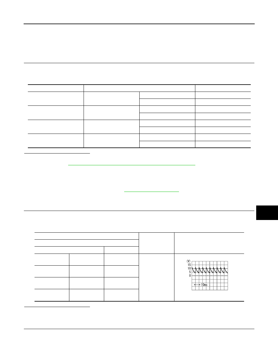
3. Check signal between malfunctioning door switch harness connector and ground using oscilloscope.

Is the inspection result normal?

YES

>> GO TO 3.

NO

>> GO TO 2.

2.

CHECK DOOR SWITCH CIRCUIT 

1. Disconnect BCM connector.

2. Check continuity between door switch harness connector and BCM harness connector.

Monitor item

Condition

Status

DOOR SW-DR

Front door LH

Open

ON

Closed

OFF

DOOR SW-AS

Front  door RH

Open

ON

Closed

OFF

DOOR SW-RL

Rear door LH

Open

ON

Closed

OFF

DOOR SW-RR

Rear door RH

Open

ON

Closed

OFF

(+)

(–)

Signal

(Reference value)

Door switch

Connector

Terminal

Front door switch 
LH

B21

3

Ground

7.0 - 8.0 V

Front door switch 
RH

B28

3

Rear door switch 
LH

B26

3

Rear door switch 
RH

B41

3

PKIB4960J

PWC-54

< DTC/CIRCUIT DIAGNOSIS >

DOOR SWITCH

3. Check continuity between door switch harness connector and ground.

Is the inspection result normal?

YES

>> Replace BCM. Refer to 

BCS-73, "Removal and Installation"

.

NO

>> Repair or replace harness.

3.

CHECK DOOR SWITCH 

Refer to 

PWC-54, "WITH INTELLIGENT KEY : Component Inspection"

.

Is the inspection result normal?

YES

>> GO TO 4.

NO

>> Replace malfunctioning door switch.

4.

CHECK INTERMITTENT INCIDENT

Refer to 

GI-39, "Intermittent Incident"

.

>> Inspection End.

WITH INTELLIGENT KEY : Component Inspection

INFOID:0000000009757270

1.

CHECK DOOR SWITCH

1. Turn ignition switch OFF.

2. Disconnect malfunctioning door switch connector.

3. Check continuity between door switch terminals.

Is the inspection result normal?

Door switch

BCM

Continuity 

Connector

Terminal

Connector

Terminal

Front door switch 
LH

B21

3

B24

98

Yes

Front door switch 
RH

B28

100

Rear door switch  
LH

B26

97

Rear door switch 
RH

B41

99

Door switch

Ground

Continuity 

Connector

Terminal

Front door switch LH

B21

3

No

Front door switch RH

B28

Rear door switch LH

B26

Rear door switch RH

B41

Door switch

Condition

Continuity

Terminal

Front door switch 
LH

3

Ground part of door 

switch

Door switch

Pressed

No

Released

Yes

Front door switch 
RH

Pressed

No

Released

Yes

Rear door switch 
LH

Pressed

No

Released

Yes

Rear door switch 
RH

Pressed

No

Released

Yes

DOOR SWITCH

PWC-55

< DTC/CIRCUIT DIAGNOSIS >

C

D

E

F

G

H

I

J

L

M

A

B

PWC

N

O

P

YES

>> Inspection End.

NO

>> Replace malfunction door switch.

WITHOUT INTELLIGENT KEY
WITHOUT INTELLIGENT KEY : Description

INFOID:0000000009757271

Detects door open/close condition.

WITHOUT INTELLIGENT KEY : Component Function Check

INFOID:0000000009757272

1.

CHECK FUNCTION

 With CONSULT

Check door switches DOOR SW-DR, DOOR SW-AS, DOOR SW-RL, DOOR SW-RR in Data Monitor mode

with CONSULT.

Is the inspection result normal?

YES

>> Door switch is OK.

NO

>> Refer to 

PWC-55, "WITHOUT INTELLIGENT KEY : Diagnosis Procedure"

.

WITHOUT INTELLIGENT KEY : Diagnosis Procedure

INFOID:0000000009757273

Regarding Wiring Diagram information, refer to 

DLK-224, "Wiring Diagram"

.

1.

CHECK DOOR SWITCH INPUT SIGNAL

1. Turn ignition switch OFF.

2. Check signal between BCM connector and ground with oscilloscope.

Monitor item

Condition

DOOR SW-DR

CLOSE 

→ OPEN: OFF → ON

DOOR SW-AS

DOOR SW-RL

DOOR SW-RR

PWC-56

< DTC/CIRCUIT DIAGNOSIS >

DOOR SWITCH

Is the inspection result normal?

YES

>> GO TO 4

NO

>> GO TO 2

2.

CHECK DOOR SWITCH CIRCUIT 

1. Disconnect BCM connector.

2. Check continuity between BCM connector and door switch connector.

Terminals

Door condition

Voltage (V)

(Approx.)

(+)

(–)

BCM

connector

Terminal

B57

45

Ground

Front RH

OPEN

0

CLOSE

7.0 - 8.0 V

48

Rear RH

OPEN

0

CLOSE

7.0 - 8.0 V

46

Front LH

OPEN

0

CLOSE

7.0 - 8.0 V

47

Rear LH

OPEN

0

CLOSE

7.0 - 8.0 V

PKIB4960J

PKIB4960J

PKIB4960J

PKIB4960J


Content   ..  712  713  714  715   ..