Nissan Sentra. Manual - part 677


  Index      Nissan     Nissan Sentra (2014 year) - Service and Repair Manual


Search            


Content   ..  675  676  677  678   ..


Nissan Sentra. Manual - part 677


PCS

COMPONENT PARTS

PCS-61

< SYSTEM DESCRIPTION >

[POWER DISTRIBUTION SYSTEM]

C

D

E

F

G

H

I

J

K

L

B

A

O

P

N

SYSTEM DESCRIPTION

COMPONENT PARTS

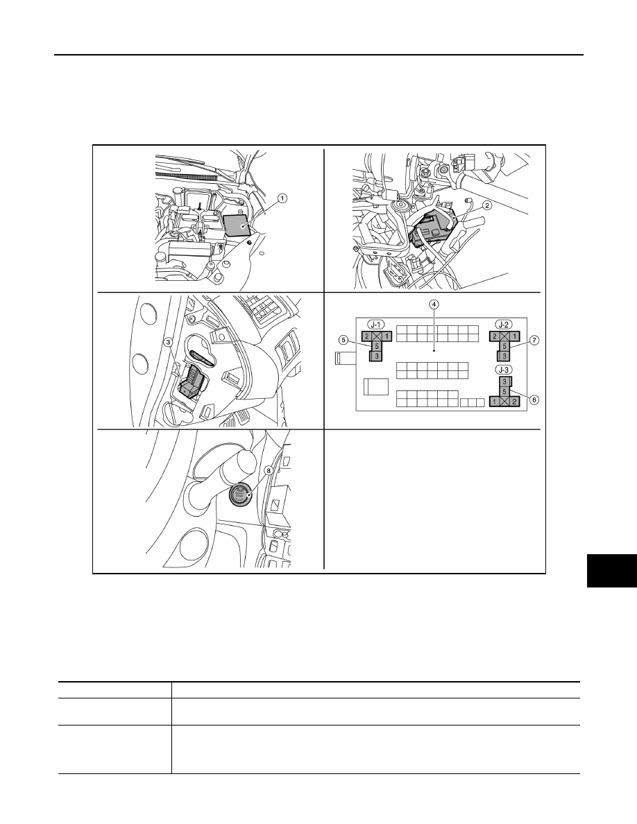
Component Parts Location

INFOID:0000000009755854

Component Description

INFOID:0000000009755855

AWMIA1369ZZ

1.

IPDM E/R (contains Ignition relay-1)

2.

BCM (view with instrument panel re-
moved)

3.

Fuse block (J/B) (front)

4.

Fuse block (J/B) (back)

5.

Blower relay

6.

Ignition relay-2

7.

Accessory relay-1

8.

Push-button ignition switch

Component

Description

Push-button ignition switch

Push-button ignition switch (push switch) is pressed, and transmits the status signal to BCM and IPDM 
E/R.

IPDM E/R

• IPDM E/R detects push-button ignition switch (push switch) status, and transmits push-button ignition 

switch status signal (CAN) to BCM.

• IPDM E/R receives ignition relay (IPDM E/R) control signal and ignition switch ON signal (CAN) from 

BCM, and controls ignition relay (built in IPDM E/R)

PCS-62

< SYSTEM DESCRIPTION >

[POWER DISTRIBUTION SYSTEM]

COMPONENT PARTS

BCM

• BCM controls power distribution system.
• BCM judges ignition switch position by push-button ignition switch (push switch) and vehicle condition
• BCM checks the ignition switch position internally.

Blower relay (in fuse block)

• Blower relay is controlled by BCM.
• Blower relay supplies the ignition switch ON power supply or the ignition switch ON signal to air con-

ditioning system when ignition switch is turned ON.

• BCM compares status of blower relay control signal and ignition switch position judged by BCM.

Accessory relay-1 (in fuse 
block)

• Accessory relay is controlled by BCM.
• Accessory relay supplies the accessory power supply or the ignition switch ACC signal to each ECU 

when ignition switch is turned ACC or ON.

• BCM compares status of accessory relay control signal, and ignition switch position judged by BCM.

Ignition relay-2 (in fuse 
block)

• Ignition relay is controlled by BCM.
• Ignition relay supplies the ignition switch ON power supply or the ignition switch ON signal to each 

ECU and system when ignition switch is turned ON.

• BCM compares status of ignition relay control signal and ignition switch position judged by BCM.
• BCM monitors the ignition relay operating status by the ignition relay feedback signal. 

Component

Description

PCS

SYSTEM

PCS-63

< SYSTEM DESCRIPTION >

[POWER DISTRIBUTION SYSTEM]

C

D

E

F

G

H

I

J

K

L

B

A

O

P

N

SYSTEM

POWER DISTRIBUTION SYSTEM
POWER DISTRIBUTION SYSTEM : System Diagram

INFOID:0000000009755856

POWER DISTRIBUTION SYSTEM : System Description

INFOID:0000000009755857

SYSTEM DESCRIPTION

• PDS (POWER DISTRIBUTION SYSTEM) is the system that BCM controls with the operation of the push-

button ignition switch and performs the power distribution to each power circuit. This system is used instead

of the mechanical power supply changing mechanism with the operation of the conventional key cylinder.

• The push-button ignition switch can be operated when Intelligent Key is in the following condition.

- Intelligent Key is in the detection area of the inside key antenna.

- Intelligent Key backside is contacted to push-button ignition switch.

• The push-button ignition switch operation is input to BCM as a signal. BCM changes the power supply posi-

tion according to the status and operates the following relays to supply power to each power circuit.

- Ignition relay-1

- Ignition relay-2

- Accessory relay-1

- Accessory relay-2

- Blower relay

NOTE:

The engine switch operation changes due to the conditions of brake pedal, selector lever and vehicle speed.

• The power supply position can be confirmed with the lighting of the indicators in the push-button ignition

switch.

BATTERY SAVER SYSTEM

When all the following conditions are met for 30 minutes, the battery saver system will cut off the power supply

to prevent battery discharge.

• The ignition switch is in the ACC or ON position

• All doors are closed

• Selector lever is in the P (park) position

Reset Condition of Battery Saver System

In order to prevent the battery from discharging, the battery saver system will cut off the power supply when all

doors are closed, the selector lever is in P (park) position and the ignition switch is left in the ACC or ON posi-

tion for 30 minutes. If any of the following conditions are met the battery saver system is released and the

steering will change automatically to lock position from OFF position.

• Opening any door

• Operating door request switch on door handle

• Operating Intelligent Key

AWMIA1512GB

PCS-64

< SYSTEM DESCRIPTION >

[POWER DISTRIBUTION SYSTEM]

SYSTEM

POWER SUPPLY POSITION CHANGE TABLE BY PUSH-BUTTON IGNITION SWITCH OPERA-
TION

The power supply position changing operation can be performed with the following operations.

NOTE:

• When an Intelligent Key is within the detection area of inside key antenna and when Intelligent Key backside

is contacted to push-button ignition switch, it is equivalent to the operations below.

• When starting the engine, the BCM monitors under the engine start conditions:

- Brake pedal operating condition

- Selector lever position

- Vehicle speed

Vehicle speed: less than 4 km/h (2.5 MPH)

Vehicle speed: 4 km/h (2.5 MPH) or more

Emergency stop operation
• Press and hold the push-button ignition switch for 2 seconds or more.
• Press the push-button ignition switch 3 times or more within 1.5 seconds.

Power supply position

Engine start/stop condition

Push-button ignition switch 

operation frequency

Selector lever position

Brake pedal operation condition

OFF 

→ ACC

Not depressed

1

OFF 

→ ACC → ON

Not depressed

2

OFF 

→ ACC → ON → OFF

Not depressed

3

OFF 

→ START

ACC 

→ START

ON 

→ START

P or N position

Depressed

1

Engine is running 

→ OFF

1

Power supply position

Engine start/stop condition

Push-button ignition switch 

operation frequency

Selector lever position

Brake pedal operation condition

Engine is running 

→ ACC 

Emergency stop operation

Engine stall return operation 
while driving 

N position

Not depressed

1


Content   ..  675  676  677  678   ..