Nissan Sentra. Manual - part 669


  Index      Nissan     Nissan Sentra (2014 year) - Service and Repair Manual


Search            


Content   ..  667  668  669  670   ..


Nissan Sentra. Manual - part 669


PCS

POWER SUPPLY AND GROUND CIRCUIT

PCS-29

< DTC/CIRCUIT DIAGNOSIS >

[IPDM E/R (WITH I-KEY)]

C

D

E

F

G

H

I

J

K

L

B

A

O

P

N

POWER SUPPLY AND GROUND CIRCUIT

Diagnosis Procedure

INFOID:0000000009755826

Regarding Wiring Diagram information, refer to 

PCS-21, "Wiring Diagram"

.

1.

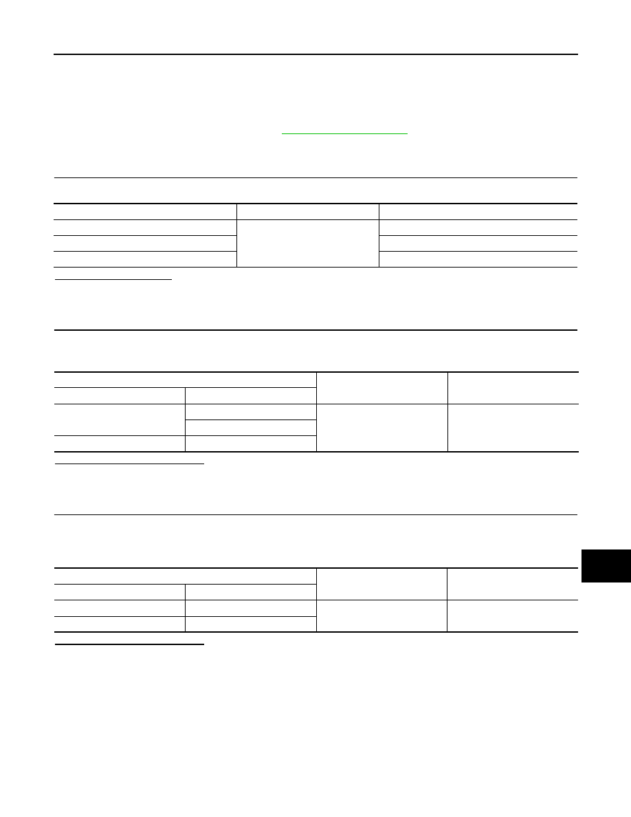
 CHECK FUSE AND FUSIBLE LINKS

Check that the following IPDM E/R fusible links are not blown.

Is the fusible link blown?

YES

>> Replace the blown fusible link after repairing the affected circuit.

NO

>> GO TO 2

2.

 CHECK POWER SUPPLY CIRCUIT

1. Disconnect IPDM E/R connector E42 and E44.

2. Check voltage between IPDM E/R connector E42 and E44 and ground.

Is the inspection result normal?

YES

>> GO TO 3

NO

>> Repair harness or connectors.

3.

 CHECK GROUND CIRCUIT

1. Turn ignition switch OFF.

2. Disconnect IPDM E/R connector E47 and E48.

3. Check continuity between IPDM E/R connector E47 and E48 and ground.

Is the inspection result normal?

YES

>> Inspection End.

NO

>> Repair harness or connectors.

Terminal No.

Signal name

Fusible link Nos.

1

Battery

E (80A)

2

B (60A)

24

J (40A/50A)

IPDM E/R

Ground

Voltage

Connector

Terminal

E42

1

Battery voltage

2

E44

24

IPDM E/R

Ground

Continuity

Connector

Terminal

E47

52

Yes

E48

57

PCS-30

< REMOVAL AND INSTALLATION >

[IPDM E/R (WITH I-KEY)]

IPDM E/R

REMOVAL AND INSTALLATION

IPDM E/R

Exploded View

INFOID:0000000009755827

Removal and Installation

INFOID:0000000009755828

CAUTION:

IPDM E/R integrated relays are not serviceable and must not be removed from unit.

REMOVAL

1. Remove inlet air duct (upper). Refer to 

EM-25, "Removal and Installation"

.

2. Remove battery. Refer to 

PG-50, "Removal and Installation (Battery)"

.

3. Release pawls (A) on IPDM E/R cover and remove IPDM E/R

(1) from IPDM E/R cover B (2).

4. Disconnect harness connector and then remove IPDM E/R.
5. Remove engine room harness from IPDM E/R cover B.

1. IPDM E/R

2. IPDM E/R cover A

3. IPDM E/R cover B

JMMIA0882ZZ

JMMIA0883ZZ

PCS

IPDM E/R

PCS-31

< REMOVAL AND INSTALLATION >

[IPDM E/R (WITH I-KEY)]

C

D

E

F

G

H

I

J

K

L

B

A

O

P

N

6. Remove IPDM E/R cover B nuts (A).

7. Insert a suitable tool (A) between IPDM E/R cover A (1) and

IPDM E/R cover B (2), disengage pawls, and remove IPDM E/R

cover A.

8. Remove IPDM E/R cover B.

INSTALLATION

Installation is in the reverse order of removal.

JMMIA0884ZZ

JMMIA0461ZZ

PCS-32

< PRECAUTION >

[IPDM E/R (WITHOUT I-KEY)]

PRECAUTIONS

PRECAUTION

PRECAUTIONS

Precaution for Supplemental Restraint System (SRS) "AIR BAG" and "SEAT BELT 
PRE-TENSIONER"

INFOID:0000000009755829

The Supplemental Restraint System such as “AIR BAG” and “SEAT BELT PRE-TENSIONER”, used along

with a front seat belt, helps to reduce the risk or severity of injury to the driver and front passenger for certain

types of collision. Information necessary to service the system safely is included in the SR and SB section of

this Service Manual.

WARNING:

• To avoid rendering the SRS inoperative, which could increase the risk of personal injury or death in

the event of a collision which would result in air bag inflation, all maintenance must be performed by

an authorized NISSAN/INFINITI dealer.

• Improper maintenance, including incorrect removal and installation of the SRS, can lead to personal

injury caused by unintentional activation of the system. For removal of Spiral Cable and Air Bag

Module, see the SR section.

• Do not use electrical test equipment on any circuit related to the SRS unless instructed to in this

Service Manual. SRS wiring harnesses can be identified by yellow and/or orange harnesses or har-

ness connectors.

PRECAUTIONS WHEN USING POWER TOOLS (AIR OR ELECTRIC) AND HAMMERS

WARNING:

• When working near the Airbag Diagnosis Sensor Unit or other Airbag System sensors with the Igni-

tion ON or engine running, DO NOT use air or electric power tools or strike near the sensor(s) with a

hammer. Heavy vibration could activate the sensor(s) and deploy the air bag(s), possibly causing

serious injury.

• When using air or electric power tools or hammers, always switch the Ignition OFF, disconnect the

battery and wait at least three minutes before performing any service.


Content   ..  667  668  669  670   ..