Nissan Sentra. Manual - part 653
MWI-58
< DTC/CIRCUIT DIAGNOSIS >
FUEL LEVEL SENSOR SIGNAL CIRCUIT
FUEL LEVEL SENSOR SIGNAL CIRCUIT
Description
INFOID:0000000009758282
The fuel level sensor unit and fuel pump detects the approximate fuel level in the fuel tank and transmits the
fuel level signal to the combination meter.
Component Function Check
INFOID:0000000009758283
1.
COMBINATION METER INPUT SIGNAL
1. Select METER/M&A on CONSULT.
2. Using FUEL METER of DATA MONITOR, compare the value of DATA MONITOR with fuel gauge pointer
of combination meter.
Does the data monitor value approximately match the fuel gauge indication?
YES
>> Inspection End.
NO
>> Replace combination meter. Refer to
MWI-77, "Removal and Installation"
Diagnosis Procedure
INFOID:0000000009758284
Regarding Wiring Diagram information, refer to
.
1.
CHECK FUEL LEVEL SENSOR CIRCUIT
1. Turn ignition switch OFF.
2. Disconnect combination meter connector and fuel level sensor unit connector.
3. Check continuity between combination meter harness connector and fuel level sensor unit harness con-
nector.
4. Check continuity between combination meter harness connector and ground.
Is the inspection result normal?
YES
>> GO TO 2.
NO
>> Repair or replace harness or connector.
2.
CHECK FUEL LEVEL SENSOR GROUND CIRCUIT
1. Check continuity between fuel level sensor unit harness connector and combination meter harness con-
nector.
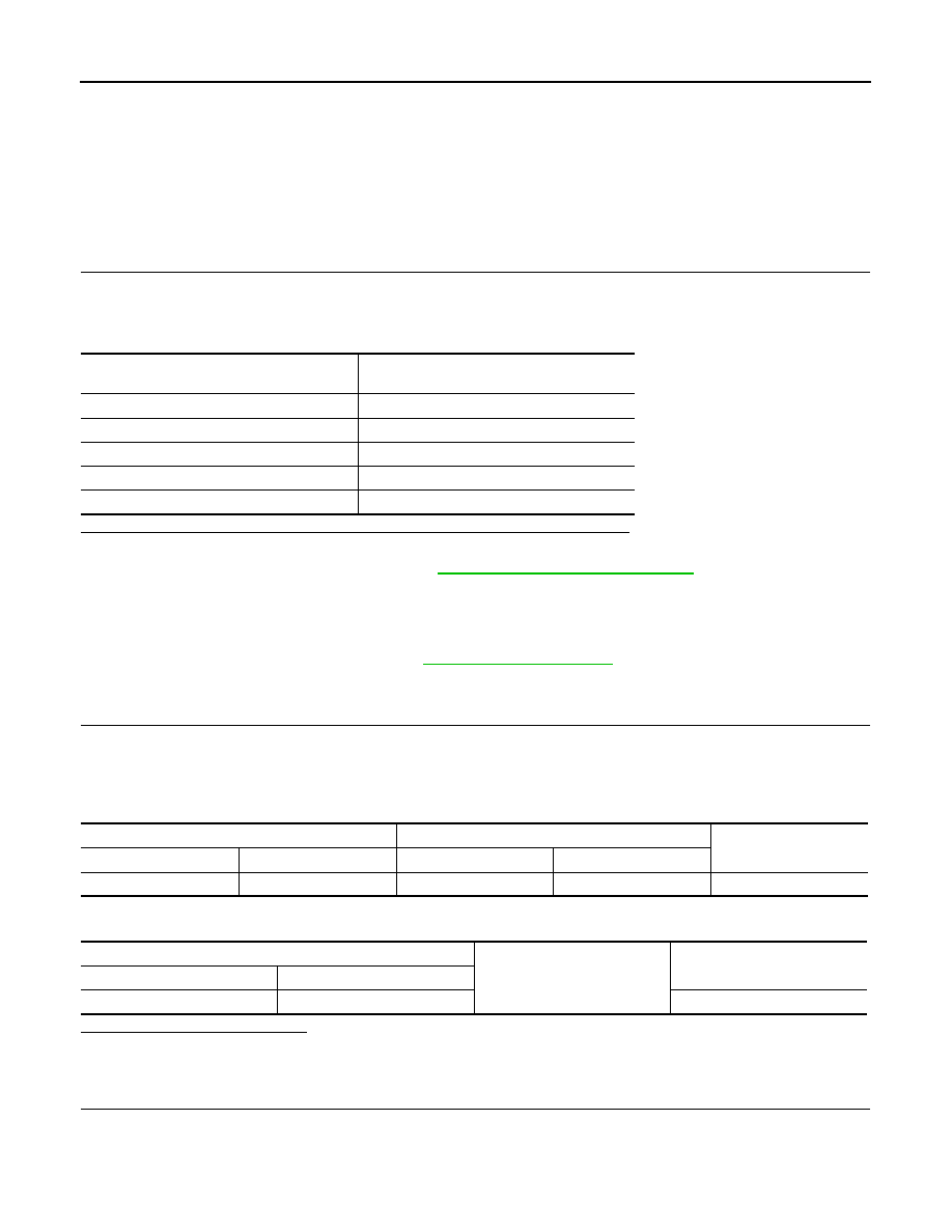
Fuel gauge pointer
Fuel tank volume [L]
(Approx.)
Full
47.2
3/4
38.4
1/2
26
1/4
13.9
Empty
0.0
Combination meter
Fuel level sensor unit
Continuity
Connector
Terminal
Connector
Terminal
M24
6
B48
2
Yes
Combination meter
Ground
Continuity
Connector
Terminal
M24
6
No