Nissan Sentra. Manual - part 641
MWI-10
< SYSTEM DESCRIPTION >
SYSTEM
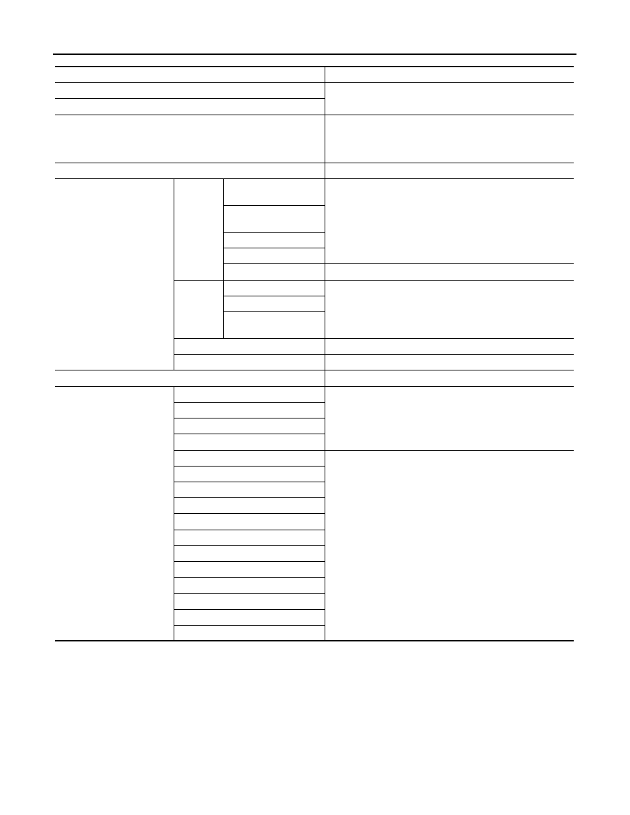
SPEEDOMETER
Function
Specifications
Speedometer
Reset to zero by suspending communication.
Tachometer
Engine coolant temperature gauge
• When reception time of an abnormal signal is 60 seconds or
less, the last value received.
• When reception time of an abnormal signal is more than 60
seconds, reset to zero.
Illumination control
When suspending communication, changes to nighttime mode.
Information display
Trip com-
puter
Current fuel consump-
tion
The last result calculated during normal condition is indicated.
Average fuel consump-
tion
Average vehicle speed
Distance to empty
ECO pedal guide
The guide turns OFF by suspending communication.
Warning/
Indicator
ECO mode indicator
The lamp turns OFF by suspending communication.
Gear shift indicator
ECO pedal guide indica-
tor
Shift position indicator
When suspending communication, not indicate.
Odo/trip meter
An indicated value is maintained at communications blackout.
Buzzer
The buzzer turns OFF by suspending communication.
Warning lamp/indicator lamp
ABS warning lamp
The lamp turns ON by suspending communication.
EPS warning lamp
Malfunction indicator lamp (MIL)
Brake warning lamp
High beam indicator lamp
The lamp turns OFF by suspending communication.
Turn signal indicator lamp
Door warning lamp
Position lamp indicator lamp
Engine start operation indicator lamp
Shift P warning lamp
Front fog lamp indicator lamp
Rear fog lamp indicator lamp
Engine Oil pressure warning lamp
KEY warning lamp
CRUISE indicator lamp
SPORT indicator lamp