Nissan Sentra. Manual - part 569
HAC-124
< SYSTEM DESCRIPTION >
[MANUAL AIR CONDITIONER]
SYSTEM
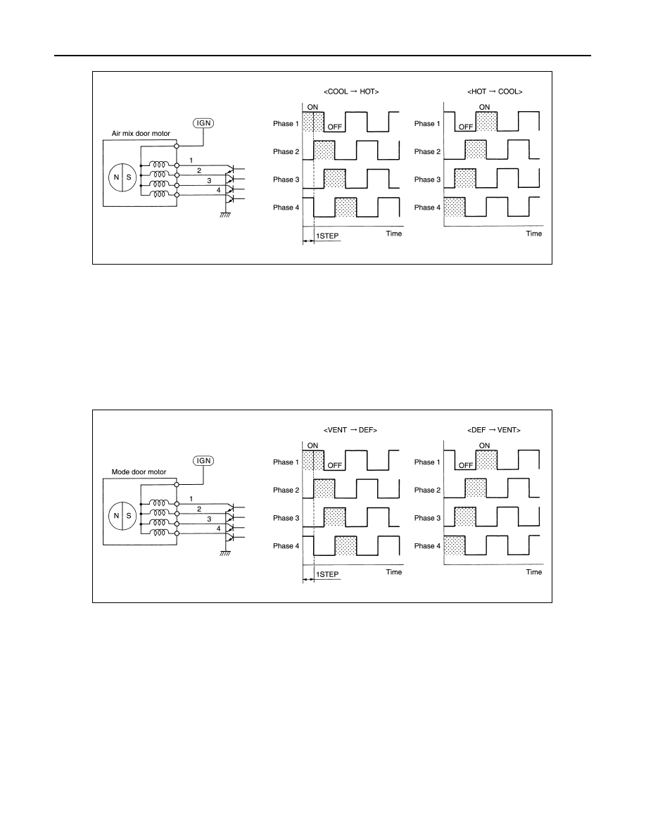
• Direction of rotation is changeable by recomposing pattern of excitation.
MODE DOOR MOTOR
DESCRIPTION
• The step motor system is adopted for mode door motor.
• When a drive signal is input from A/C auto amp. to door motor, a step motor built into the door motor rotates
according to the drive signal, and then stops at the target door position.
• Rotation of motor is transmitted to mode door (center ventilator and defroster door, sub defroster door, side
ventilator door, and foot door) by link, rod, and lever, then air outlet is switched.
DRIVE METHOD
• The 4 drive coils are excited in sequence in order to drive the motor.
• Direction of rotation is changeable by recomposing pattern of excitation.
INTAKE DOOR MOTOR
• Motor operates intake door according to control signal from A/C auto amp.
• Rotation of motor is transmitted to intake door by lever, then air inlet is switched.
SWITCHES AND THEIR CONTROL FUNCTION
JSIIA1655GB
JZIIA0033GB