Nissan Sentra. Manual - part 561


  Index      Nissan     Nissan Sentra (2014 year) - Service and Repair Manual


Search            


Content   ..  559  560  561  562   ..


Nissan Sentra. Manual - part 561


HAC-92

< DTC/CIRCUIT DIAGNOSIS >

[AUTOMATIC AIR CONDITIONER]

BLOWER MOTOR

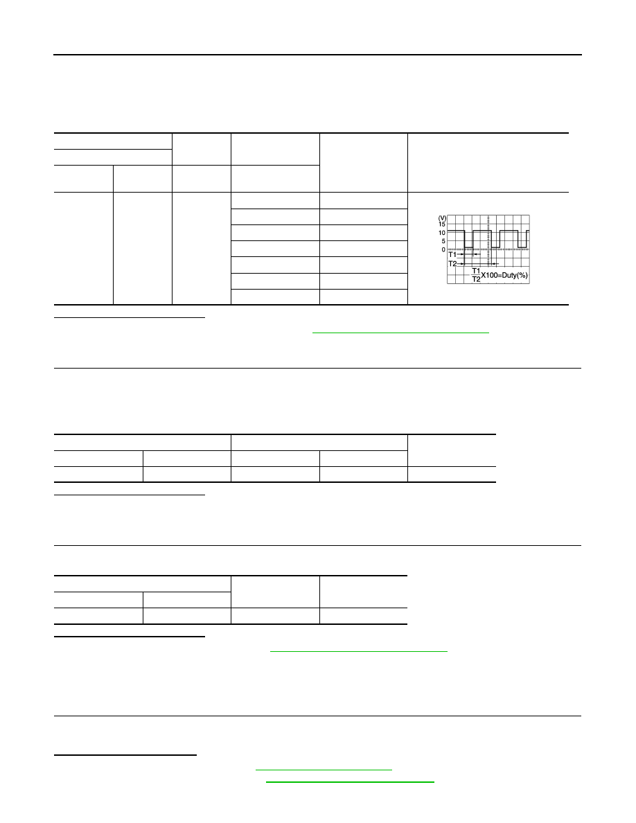
4. Change fan speed from 1st – 7th, and check duty ratios between variable blower control harness connec-

tor and ground by using an oscilloscope. 

NOTE:

Calculate the drive signal duty ratio as shown in the figure.

T2 = Approx. 1.6 ms

Is the inspection result normal?

YES

>> Replace variable blower control. Refer to 

HAC-113, "Removal and Installation"

.

NO

>> GO TO 10.

10.

CHECK VARIABLE BLOWER CONTROL CONTROL SIGNAL CIRCUIT FOR OPEN

1. Turn ignition switch OFF.

2. Disconnect variable blower control connector and A/C auto amp. connector.

3. Check continuity between variable blower control harness connector and A/C auto amp. harness connec-

tor. 

Is the inspection result normal?

YES

>> GO TO 11.

NO

>> Repair harness or connector.

11.

CHECK VARIABLE BLOWER CONTROL CONTROL SIGNAL CIRCUIT FOR SHORT

Check continuity between variable blower control harness connector and ground. 

Is the inspection result normal?

YES

>> Replace A/C auto amp. Refer to 

HAC-105, "Removal and Installation"

.

NO

>> Repair harness or connector.

Component Inspection (Blower Motor)

INFOID:0000000009757688

1.

CHECK BLOWER MOTOR

1. Connect battery voltage to terminal 1 of blower motor.

2. Connect ground to terminal 2 of blower motor.
Does the blower fan operate?

YES

>> Intermittent incident. Refer to 

GI-39, "Intermittent Incident"

.

NO

>> Replace blower motor. Refer to 

VTL-10, "Removal and Installation"

.

+

Condition

Duty ratio

(Approx.)

Output waveform

Variable blower control

Connector

Terminal

Fan speed (manual) 

Air outlet: VENT

M52

2

Ground

1st

26%

2nd

34%

3rd

41%

4th

51%

5th

62%

6th

73%

7th

82%

JPIIA1646GB

Variable blower control

A/C auto amp.

Continuity

Connector

Terminal

Connector

Terminal

M52

2

M34

13

Yes

Variable blower control

Continuity

Connector

Terminal

M52

2

Ground

No

BLOWER MOTOR

HAC-93

< DTC/CIRCUIT DIAGNOSIS >

[AUTOMATIC AIR CONDITIONER]

C

D

E

F

G

H

J

K

L

M

A

B

HAC

N

O

P

Component Inspection (Blower Motor Relay)

INFOID:0000000009757689

1.

CHECK BLOWER RELAY

1. Turn ignition switch OFF. 

2. Remove blower motor relay. 

3. Check continuity between blower motor relay terminals 3 and 5

when voltage is supplied between terminals 1 and 2. 

Is the inspection result normal?

YES

>> Inspection End.

NO

>> Replace blower motor relay.

Terminals

Voltage

Continuity

3

5

ON

Yes

OFF

No

JSIIA1551ZZ

HAC-94

< DTC/CIRCUIT DIAGNOSIS >

[AUTOMATIC AIR CONDITIONER]

MAGNET CLUTCH

MAGNET CLUTCH

Component Function Check

INFOID:0000000009757690

1.

CHECK MAGNET CLUTCH OPERATION

Perform auto active test of IPDM E/R. Refer to 

PCS-9, "Diagnosis Description"

.

Does it operate normally?

YES

>> Inspection End.

NO

>> Refer to 

HAC-94, "Diagnosis Procedure"

.

Diagnosis Procedure

INFOID:0000000009757691

Regarding Wiring Diagram information, refer to 

HAC-41, "Wiring Diagram"

.

1.

CHECK FUSE

1. Turn ignition switch OFF.

2. Check 10A fuse (No. 39, located in IPDM E/R). 

NOTE:

Refer to 

PG-49, "IPDM E/R Terminal Arrangement"

Is the inspection result normal?

YES

>> GO TO 2.

NO

>> Replace the blown fuse after repairing the affected circuit.

2.

CHECK MAGNET CLUTCH POWER SUPPLY CIRCUIT

1. Disconnect compressor connector and IPDM E/R connector.

2. Check continuity between compressor harness connector and IPDM E/R harness connector. 

Is the inspection result normal?

YES

>> GO TO 3.

NO

>> Repair harness or connector. 

3.

CHECK MAGNET CLUTCH GROUND CIRCUIT

1. Disconnect compressor connector.

2. Check continuity between compressor harness connector and ground. 

Is the inspection result normal?

YES

>> GO TO 4.

NO

>> Repair harness or connector. 

4.

CHECK MAGNET CLUTCH

Directly apply battery voltage to the magnet clutch. Check operation visually and by sound. 
Does it operate normally?

YES

>> Replace IPDM E/R. Refer to 

PCS-30, "Removal and Installation"

.

NO

>> Replace magnet clutch. Refer to 

HA-31, "MAGNET CLUTCH : Removal and Installation"

.

Compressor

IPDM E/R

Continuity

Connector

Terminal

Connector

Terminal

F3

1

E43

12

Yes

Compressor

Continuity

Connector

Terminal

F3

2

Ground

Yes

ECV (ELECTRICAL CONTROL VALVE)

HAC-95

< DTC/CIRCUIT DIAGNOSIS >

[AUTOMATIC AIR CONDITIONER]

C

D

E

F

G

H

J

K

L

M

A

B

HAC

N

O

P

ECV (ELECTRICAL CONTROL VALVE)

Diagnosis Procedure

INFOID:0000000009757692

Regarding Wiring Diagram information, refer to 

HAC-41, "Wiring Diagram"

.

1.

CHECK ECV (ELECTRICAL CONTROL VALVE) POWER SUPPLY

1. Turn ignition switch OFF.

2. Disconnect compressor connector.

3. Turn ignition switch ON.

4. Check voltage between compressor harness connector and ground.

Is the inspection result normal?

YES

>> GO TO 3.

NO

>> GO TO 2.

2.

CHECK FUSE

1. Turn ignition switch OFF.

2. Check 10 A fuse [No. 5, located in fuse block (J/B)]. Refer to 

PG-47, "Terminal Arrangement"

Is the inspection result normal?

YES

>> Repair harness or connector.

NO

>> Replace the blown fuse after repairing the affected circuit.

3.

CHECK ECV CONTROL SIGNAL CIRCUIT FOR OPEN

1. Turn ignition switch OFF.

2. Disconnect A/C auto amp. connector.

3. Check continuity between compressor harness connector and A/C auto amp. harness connector.

Is the inspection result normal?

YES

>> GO TO 4.

NO

>> Repair harness or connector.

4.

CHECK ECV CONTROL SIGNAL CIRCUIT FOR SHORT

Check continuity between compressor harness connector and ground.

Is the inspection result normal?

YES

>> GO TO 5.

NO

>> Repair harness or connector.

5.

CHECK ECV

Check ECV. Refer to 

HAC-96, "Component Inspection"

.

+

Voltage

Compressor

Connector

Terminal

F10

3

Ground

Battery voltage

Compressor

A/C auto amp.

Continuity

Connector

Terminal

Connector

Terminal

F10

4

M34

1

Yes

Compressor

Continuity

Connector

Terminal

F10

4

Ground

No


Content   ..  559  560  561  562   ..