Nissan Sentra. Manual - part 541
HAC-12
< SYSTEM DESCRIPTION >
[AUTOMATIC AIR CONDITIONER]
SYSTEM
SYSTEM
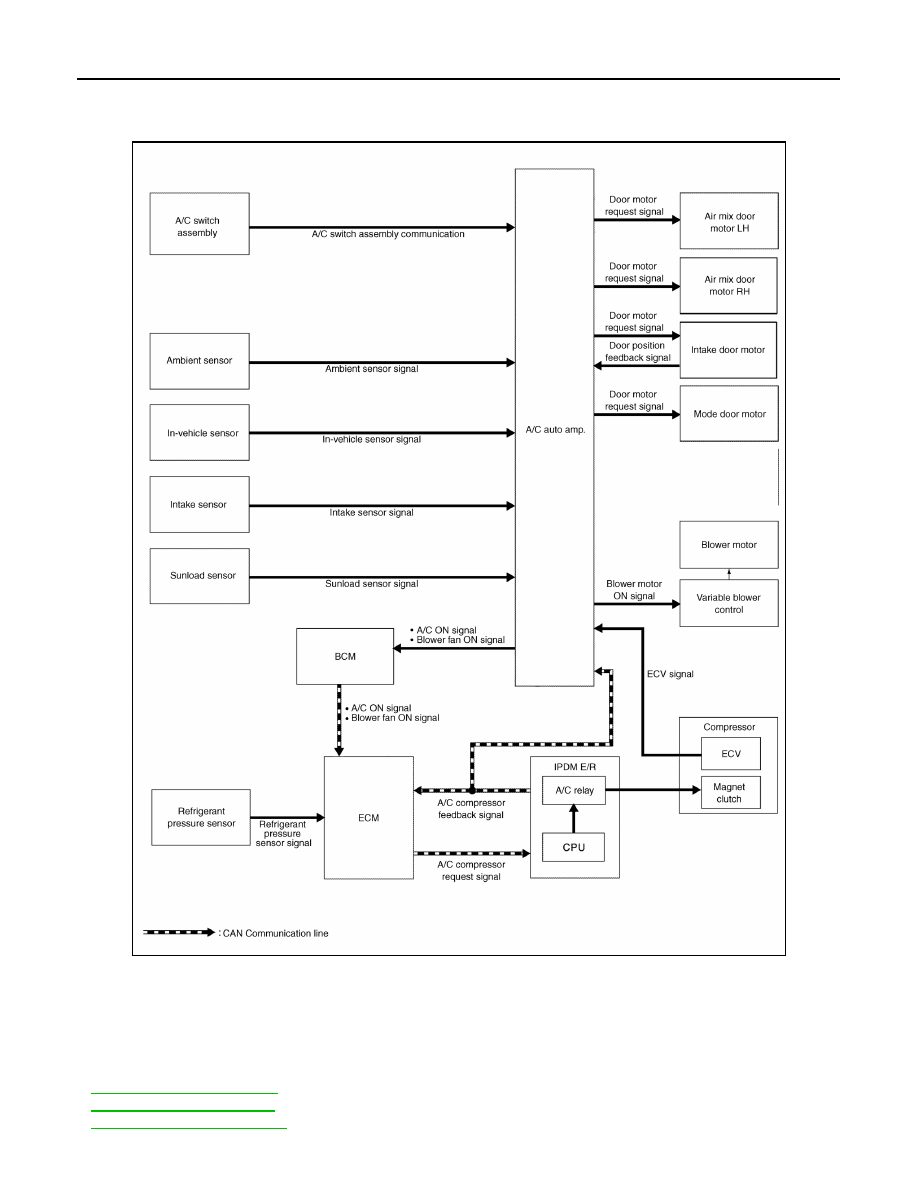
System Diagram
INFOID:0000000009757619
System Description
INFOID:0000000009757620
• Automatic air conditioning system is controlled by each function of A/C auto amp., ECM, IPDM E/R and
BCM.
Control by A/C auto amp.
-
-
-
ALIIA0707GB