Nissan Sentra. Manual - part 440


  Index      Nissan     Nissan Sentra (2014 year) - Service and Repair Manual


Search            


Content   ..  438  439  440  441   ..


Nissan Sentra. Manual - part 440


EC-456

< DTC/CIRCUIT DIAGNOSIS >

[MRA8DE]

IGNITION SIGNAL

IGNITION SIGNAL

Component Function Check

INFOID:0000000009758714

1.

INSPECTION START

1. Turn ignition switch OFF.

2. Start engine.
Does the engine start?

YES

>> GO TO 2.

NO

>> Proceed to 

EC-456, "Diagnosis Procedure"

.

2.

IGNITION SIGNAL FUNCTION

With CONSULT

1. Perform “POWER BALANCE” in “ACTIVE TEST” mode of “ENGINE” using CONSULT.

2. Check that each circuit produces a momentary engine speed drop.

Without CONSULT

1. Let engine idle.

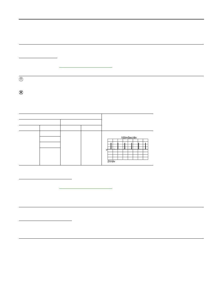
2. Check the voltage signal between ECM harness connector and ground with an oscilloscope.

NOTE:

The pulse cycle changes depending on rpm at idle.

Is the inspection result normal?

YES

>> INSPECTION END

NO

>> Proceed to 

EC-456, "Diagnosis Procedure"

.

Diagnosis Procedure

INFOID:0000000009758715

1.

CHECK FUSE

1. Turn ignition switch OFF.

2. Pull out #51 fuse and check that the fuse is not fusing.
Is the inspection result normal?

YES

>> GO TO 2.

NO

>> Replace the fuse after repairing the applicable circuit.

2.

CHECK IGNITION COIL POWER SUPPLY

1. Insert the fuse which pulled out.

2. Disconnect ignition coil harness connector.

3. Turn ignition switch ON.

4. Check the voltage between ignition coil harness connector and ground.

ECM

Voltage signal

+

Connector

Terminal

Connector

Terminal

F25

86

E16

128

87

90

91

JPBIA4733ZZ

IGNITION SIGNAL

EC-457

< DTC/CIRCUIT DIAGNOSIS >

[MRA8DE]

C

D

E

F

G

H

I

J

K

L

M

A

EC

N

P

O

Is the inspection result normal?

YES

>> GO TO 4.

NO

>> GO TO 3.

3.

CHECK IGNITION COIL POWER SUPPLY CIRCUIT

1. Turn ignition switch OFF.

2. Disconnect IPDM E/R harness connector.

3. Check the continuity between IPDM E/R harness connector and ignition coil harness connector.

4. Also check harness for short to ground.
Is the inspection result normal?

YES

>> Check intermittent incident. Refer to 

GI-39, "Intermittent Incident"

.

NO

>> Repair or replace error-detected parts.

4.

CHECK IGNITION COIL GROUND CIRCUIT

1. Turn ignition switch OFF.

2. Check the continuity between ignition coil harness connector and ground.

3. Also check harness for short to power.
Is the inspection result normal?

YES

>> GO TO 5.

NO

>> Repair or replace error-detected parts.

5.

CHECK IGNITION COIL OUTPUT SIGNAL CIRCUIT

1. Disconnect ECM harness connector.

2. Check the continuity between ECM harness connector and ignition coil harness connector.

+

Voltage

Ignition coil

Cylinder

Connector

Terminal

1

F34

3

Ground

Battery voltage

2

F35

3

3

F36

3

4

F37

3

+

Continuity

IPDM E/R

Ignition coil

Connector

Terminal

Cylinder

Connector

Terminal

E43

17

1

F34

3

Existed

2

F35

3

3

F36

3

4

F37

3

+

Continuity

Ignition coil

Cylinder

Connector

Terminal

1

F34

2

Ground

Existed

2

F35

2

3

F36

2

4

F37

2

EC-458

< DTC/CIRCUIT DIAGNOSIS >

[MRA8DE]

IGNITION SIGNAL

3. Also check harness for short to ground and short to power.
Is the inspection result normal?

YES

>> GO TO 6.

NO

>> Repair or replace error-detected parts.

6.

CHECK IGNITION COIL WITH POWER TRANSISTOR

Check ignition coil with power transistor. Refer to 

EC-459, "Component Inspection (Ignition Coil with Power

Transistor)"

.

Is the inspection result normal?

YES

>> GO TO 7.

NO

>> Replace malfunctioning ignition coil with power transistor. Refer to 

EM-45, "Exploded View"

.

7.

CHECK CONDENSER CIRCUIT

1. Turn ignition switch OFF.

2. Disconnect condenser.

3. Disconnect IPDM E/R harness connector.

4. Check the continuity between IPDM E/R harness connector and condenser harness connector.

5. Also check harness for short to ground.
Is the inspection result normal?

YES

>> GO TO 8.

NO

>> Repair or replace error-detected parts.

8.

CHECK CONDENSER GROUND CIRCUIT

1. Check the continuity between Condenser harness connector and ground.

2. Also check harness for short to power.
Is the inspection result normal?

YES

>> GO TO 9.

NO

>> Repair or replace error-detected parts.

9.

CHECK CONDENSER

Check condenser. Refer to 

EC-459, "Component Inspection (Condenser)"

.

Is the inspection result normal?

YES

>> INSPECTION END

NO

>> Replace condenser.

+

Continuity

Ignition coil

ECM

Cylinder

Connector

Terminal

Connector

Terminal

1

F34

1

F25

86

Existed

2

F35

1

87

3

F36

1

90

4

F37

1

91

+

Continuity

IPDM E/R

Condenser

Connector

Terminal

Connector

Terminal

E43

17

F4

1

Existed

+

Continuity

Condenser

Connector

Terminal

F4

2

Ground

Existed

IGNITION SIGNAL

EC-459

< DTC/CIRCUIT DIAGNOSIS >

[MRA8DE]

C

D

E

F

G

H

I

J

K

L

M

A

EC

N

P

O

Component Inspection (Condenser)

INFOID:0000000009758716

1.

CHECK CONDENSER

1. Turn ignition switch OFF.

2. Disconnect condenser harness connector.

3. Check resistance between condenser terminals as per the following.

Is the inspection result normal?

YES

>> INSPECTION END

NO

>> Replace Condenser.

Component Inspection (Ignition Coil with Power Transistor)

INFOID:0000000009758717

1.

CHECK IGNITION COIL WITH POWER TRANSISTOR-1

1. Turn ignition switch OFF.

2. Disconnect ignition coil harness connector.

3. Check resistance between ignition coil terminals as per the following.

Is the inspection result normal?

YES

>> GO TO 2.

NO

>> Replace malfunctioning ignition coil with power transistor. Refer to 

EM-45, "Exploded View"

.

2.

CHECK IGNITION COIL WITH POWER TRANSISTOR-2

CAUTION:

Do the following procedure in the place where ventilation is good without the combustible.

1. Turn ignition switch OFF.

2. Reconnect all harness connectors disconnected.

3. Remove fuel pump fuse in IPDM E/R to release fuel pressure.

NOTE:

Do not use CONSULT to release fuel pressure, or fuel pressure applies again during the following proce-

dure.

4. Start engine.

5. After engine stalls, crank it two or three times to release all fuel pressure.

6. Turn ignition switch OFF.

7. Remove all ignition coil harness connectors to avoid the electrical discharge from the ignition coils. Refer

to 

EM-45, "Exploded View"

.

8. Remove ignition coil and spark plug of the cylinder to be checked. Refer to 

EM-45, "Exploded View"

.

9. Crank engine for 5 seconds or more to remove combustion gas in the cylinder.

10. Connect spark plug and harness connector to ignition coil.

Condenser

Condition

Resistance

+

Terminal

1

2

Temperature 

°C (°F)

25 (77)

Above 1 M

Ignition coil with power tran-

sistor

Condition

Resistance

+

Terminal

1

2

Temperature   

°C (°F)

25 (77)

Except 0 or 

∞ Ω

3

Except 0 

2

3


Content   ..  438  439  440  441   ..