Nissan Sentra. Manual - part 419


  Index      Nissan     Nissan Sentra (2014 year) - Service and Repair Manual


Search            


Content   ..  417  418  419  420   ..


Nissan Sentra. Manual - part 419


EC-372

< DTC/CIRCUIT DIAGNOSIS >

[MRA8DE]

P1225 TP SENSOR

P1225 TP SENSOR

DTC Logic

INFOID:0000000009758623

DTC DETECTION LOGIC

DTC CONFIRMATION PROCEDURE

1.

PRECONDITIONING

If DTC Confirmation Procedure has been previously conducted, always perform the following procedure

before conducting the next test.

1. Turn ignition switch OFF and wait at least 10 seconds.

2. Turn ignition switch ON.

3. Turn ignition switch OFF and wait at least 10 seconds.

TESTING CONDITION:

Before performing the following procedure, confirm that battery voltage is more than 10 V at idle.

>> GO TO 2.

2.

PERFORM DTC CONFIRMATION PROCEDURE

1. Turn ignition switch ON.

2. Turn ignition switch OFF and wait at least 10 seconds.

3. Turn ignition switch ON.

4. Check 1st trip DTC.
Is 1st trip DTC detected?

YES

>> Proceed to 

EC-372, "Diagnosis Procedure"

.

NO

>> INSPECTION END

Diagnosis Procedure

INFOID:0000000009758624
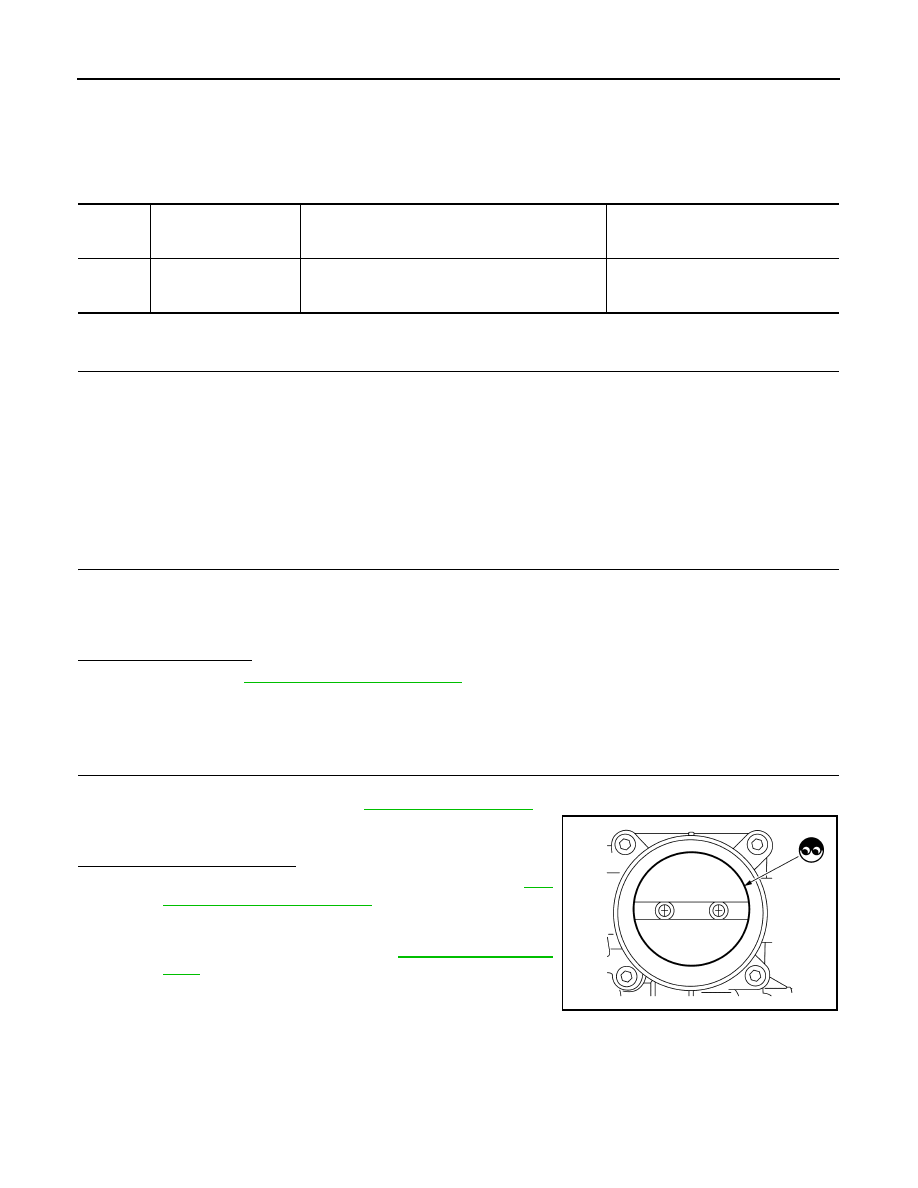
1.

CHECK ELECTRIC THROTTLE CONTROL ACTUATOR VISUALLY

1. Turn ignition switch OFF.

2. Remove the intake air duct. Refer to 

EM-25, "Exploded View"

.

3. Check if foreign matter is caught between the throttle valve and

the housing.

Is the inspection result normal?

YES

>> Replace electric throttle control actuator. Refer to 

EM-

27, "Removal and Installation"

.

NO

>> Remove the foreign matter and clean the electric throttle

control actuator inside, then perform throttle valve

closed position learning. Refer to 

EC-139, "Work Proce-

dure"

.

DTC No.

CONSULT screen terms

(Trouble diagnosis con-

tent)

DTC detecting condition

Possible cause

P1225

CTP LEARNING-B1
(Closed throttle position 
learning bank 1)

Closed throttle position learning value is excessively 
low.

Electric throttle control actuator
(TP sensor 1 and 2)

JSBIA2864ZZ

P1226 TP SENSOR

EC-373

< DTC/CIRCUIT DIAGNOSIS >

[MRA8DE]

C

D

E

F

G

H

I

J

K

L

M

A

EC

N

P

O

P1226 TP SENSOR

DTC Logic

INFOID:0000000009758625

DTC DETECTION LOGIC

DTC CONFIRMATION PROCEDURE

1.

PRECONDITIONING

If DTC Confirmation Procedure has been previously conducted, always perform the following procedure

before conducting the next test.

1. Turn ignition switch OFF and wait at least 10 seconds.

2. Turn ignition switch ON.

3. Turn ignition switch OFF and wait at least 10 seconds.

TESTING CONDITION:

Before performing the following procedure, confirm that battery voltage is more than 10 V at idle.

>> GO TO 2.

2.

PERFORM DTC CONFIRMATION PROCEDURE

1. Turn ignition switch ON.

2. Turn ignition switch OFF, wait at least 10 seconds.

3. Turn ignition switch ON.

4. Repeat steps 2 and 3 for 32 times.

5. Check 1st trip DTC.
Is 1st trip DTC detected?

YES

>> Proceed to 

EC-373, "Diagnosis Procedure"

.

NO

>> INSPECTION END

Diagnosis Procedure

INFOID:0000000009758626

1.

CHECK ELECTRIC THROTTLE CONTROL ACTUATOR VISUALLY

1. Turn ignition switch OFF.

2. Remove the intake air duct. Refer to 

EM-25, "Exploded View"

.

3. Check if foreign matter is caught between the throttle valve and

the housing.

Is the inspection result normal?

YES

>> Replace electric throttle control actuator. Refer to 

EM-

27, "Removal and Installation"

.

NO

>> Remove the foreign matter and clean the electric throttle

control actuator inside, then perform throttle valve

closed position learning. Refer to 

EC-139, "Work Proce-

dure"

.

DTC No.

CONSULT screen terms

(Trouble diagnosis content)

DTC detecting condition

Possible cause

P1226

CTP LEARNING-B1
(CTP LEARNING-B1)

Closed throttle position learning is not performed 
successfully, repeatedly.

Electric throttle control actuator
(TP sensor 1 and 2)

JSBIA2864ZZ

E

C

- 3

7

4

< DTC/CIRCUIT DIAGNOSIS >

[MRA8DE]

P1550 BATTERY CURRENT SENSOR

P1550 BATTERY CURRENT SENSOR

DTC Logic

INFOID:0000000009758627

DTC DETECTION LOGIC

DTC CONFIRMATION PROCEDURE

1.

PRECONDITIONING

If DTC Confirmation Procedure has been previously conducted, always perform the following before conduct-

ing the next test. 

1. Turn ignition switch OFF and wait at least 10 seconds.

2. Turn ignition switch ON.

3. Turn ignition switch OFF and wait at least 10 seconds.

TESTING CONDITION:

Before performing the following procedure, confirm that battery voltage is more than 8 V at idle.

>> GO TO 2.

2.

PERFORM DTC CONFIRMATION PROCEDURE

1. Start engine and wait at least 10 seconds.

2. Check 1st trip DTC.
Is 1st trip DTC detected?

YES

>> Proceed to 

EC-374, "Diagnosis Procedure"

.

NO

>> INSPECTION END

Diagnosis Procedure

INFOID:0000000009758628

1.

CHECK BATTERY CURRENT SENSOR POWER SUPPLY

1. Turn ignition switch OFF.

2. Disconnect battery current sensor harness connector.

3. Turn ignition switch ON.

4. Check the voltage between battery current sensor harness connector and ground.

Is the inspection result normal?

YES

>> GO TO 3.

NO

>> GO TO 2.

2.

CHECK SENSOR POWER SUPPLY 2 CIRCUIT

Check sensor power supply 2 circuit. Refer to 

EC-444, "Diagnosis Procedure"

.

DTC No.

CONSULT screen terms

(Trouble diagnosis content)

DTC detecting condition

Possible cause

P1550

BAT CURRENT SENSOR
(Battery current sensor)

The output voltage of the battery current 
sensor remains within the specified 
range while engine is running.

• Harness or connectors

(Battery current sensor circuit is open 
or shorted.)

• Battery current sensor
• Camshaft position sensor
• Camshaft (Intake)
• Starter motor
• Starting system circuit
• Dead (Weak) battery
• Sensor power supply 1 circuit

+

Voltage

(Approx.)

Battery current sensor

Connector

Terminal

F54

1

Ground

5.0 V

P1550 BATTERY CURRENT SENSOR

EC-375

< DTC/CIRCUIT DIAGNOSIS >

[MRA8DE]

C

D

E

F

G

H

I

J

K

L

M

A

EC

N

P

O

Is the inspection result normal?

YES

>> Perform the trouble diagnosis for power supply circuit.

NO

>> Repair or replace error-detected parts.

3.

CHECK BATTERY CURRENT SENSOR GROUND CIRCUIT

1. Turn ignition switch OFF.

2. Disconnect ECM harness connector.

3. Check the continuity between battery current sensor harness connector and ECM harness connector.

4. Also check harness for short to power.
Is the inspection result normal?

YES

>> GO TO 4.

NO

>> Repair or replace error-detected parts.

4.

CHECK BATTERY CURRENT SENSOR INPUT SIGNAL CIRCUIT

1. Check the continuity between battery current sensor harness connector and ECM harness connector.

2. Also check harness for short to ground and to power.
Is the inspection result normal?

YES

>> GO TO 5.

NO

>> Repair or replace error-detected parts

5.

CHECK BATTERY CURRENT SENSOR

Check the battery current sensor. Refer to 

EC-375, "Component Inspection (Battery Current Sensor)"

.

Is the inspection result normal?

YES

>> Check intermittent incident. Refer to 

GI-39, "Intermittent Incident"

.

NO

>> Replace battery current sensor. Refer to 

PG-53, "Removal and Installation"

.

Component Inspection (Battery Current Sensor)

INFOID:0000000009758629

1.

CHECK BATTERY CURRENT SENSOR

1. Turn ignition switch OFF.

2. Reconnect harness connectors disconnected.

3. Disconnect battery negative cable.

4. Install jumper cable between battery negative terminal and body

ground.

+

Continuity

Battery current sensor

ECM

Connector

Terminal

Connector

Terminal

F54

3

F25

62

Existed

+

Continuity

Battery current sensor

ECM

Connector

Terminal

Connector

Terminal

F54

4

F25

63

Existed

JPBIA3286ZZ


Content   ..  417  418  419  420   ..