Nissan Sentra. Manual - part 380
EC-216
< DTC/CIRCUIT DIAGNOSIS >
[MRA8DE]
P0131 A/F SENSOR 1
*2: For California
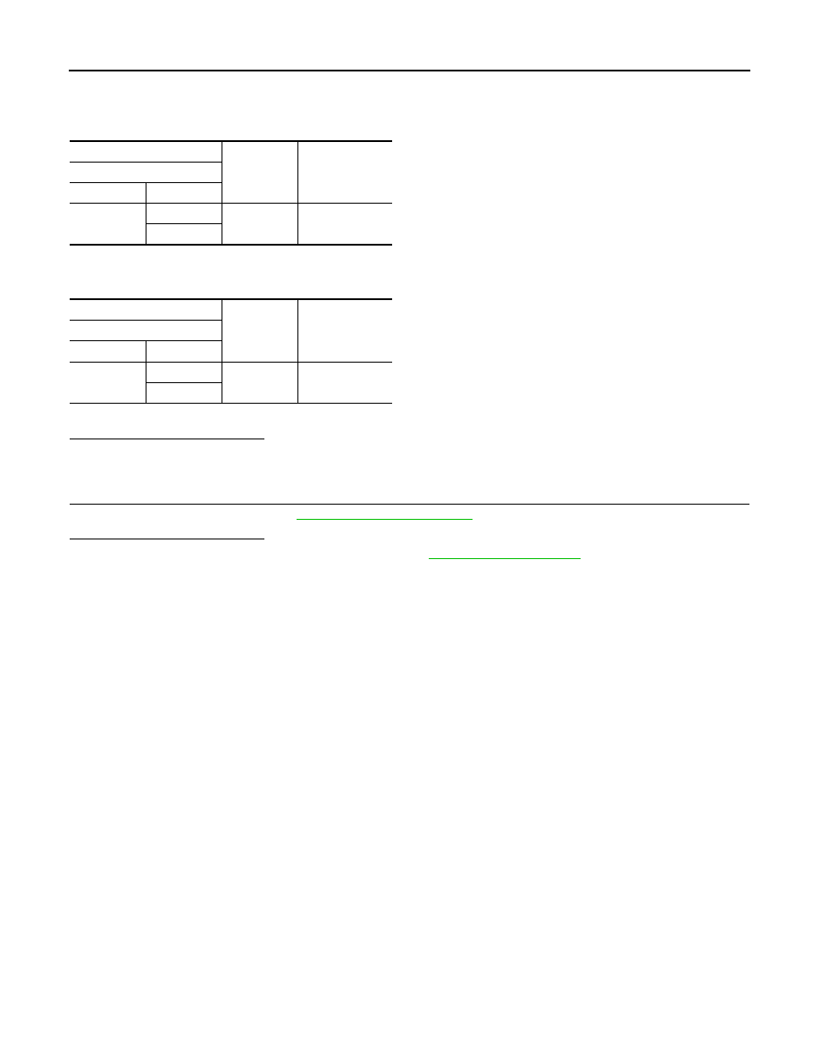
4. Check the continuity between A/F sensor 1 harness connector and ground, or ECM harness connector
and ground.
*1: Except California
*2: For California
5. Also check harness for short to power.
Is the inspection result normal?
YES
>> GO TO 4.
NO
>> Repair or replace error-detected parts.
4.
CHECK INTERMITTENT INCIDENT
Check intermittent incident. Refer to
GI-39, "Intermittent Incident"
.
Is the inspection result normal?
YES
>> Replace air fuel ratio (A/F) sensor 1. Refer to
NO
>> Repair or replace error-detected parts.
+
−
Continuity
A/F sensor 1
Connector
Terminal
F12
*1
F42
*2
1
Ground
Not existed
2
+
−
Continuity
ECM
Connector
Terminal
F24
41
Ground
Not existed
45