Nissan Sentra. Manual - part 248


  Index      Nissan     Nissan Sentra (2014 year) - Service and Repair Manual


Search            


Content   ..  246  247  248  249   ..


Nissan Sentra. Manual - part 248


DLK-108

< DTC/CIRCUIT DIAGNOSIS >

[WITH INTELLIGENT KEY SYSTEM]

REMOTE KEYLESS ENTRY RECEIVER

REMOTE KEYLESS ENTRY RECEIVER

Component Function Check

INFOID:0000000009756411

1.

CHECK FUNCTION

1. Select INTELLIGENT KEY of BCM using CONSULT.

2. Select RKE OPE COUN1 in DATA MONITOR mode.

3. Check that the function operates normally according to the following conditions.

Is the inspection result normal?

YES

>> Remote keyless entry receiver is OK.

NO    >> Refer to 

DLK-108, "Diagnosis Procedure"

.

Diagnosis Procedure

INFOID:0000000009756412

Regarding Wiring Diagram information, refer to 

DLK-49, "Wiring Diagram"

.

1.

CHECK REMOTE KEYLESS ENTRY RECEIVER OUTPUT SIGNAL

1. Turn ignition switch OFF.

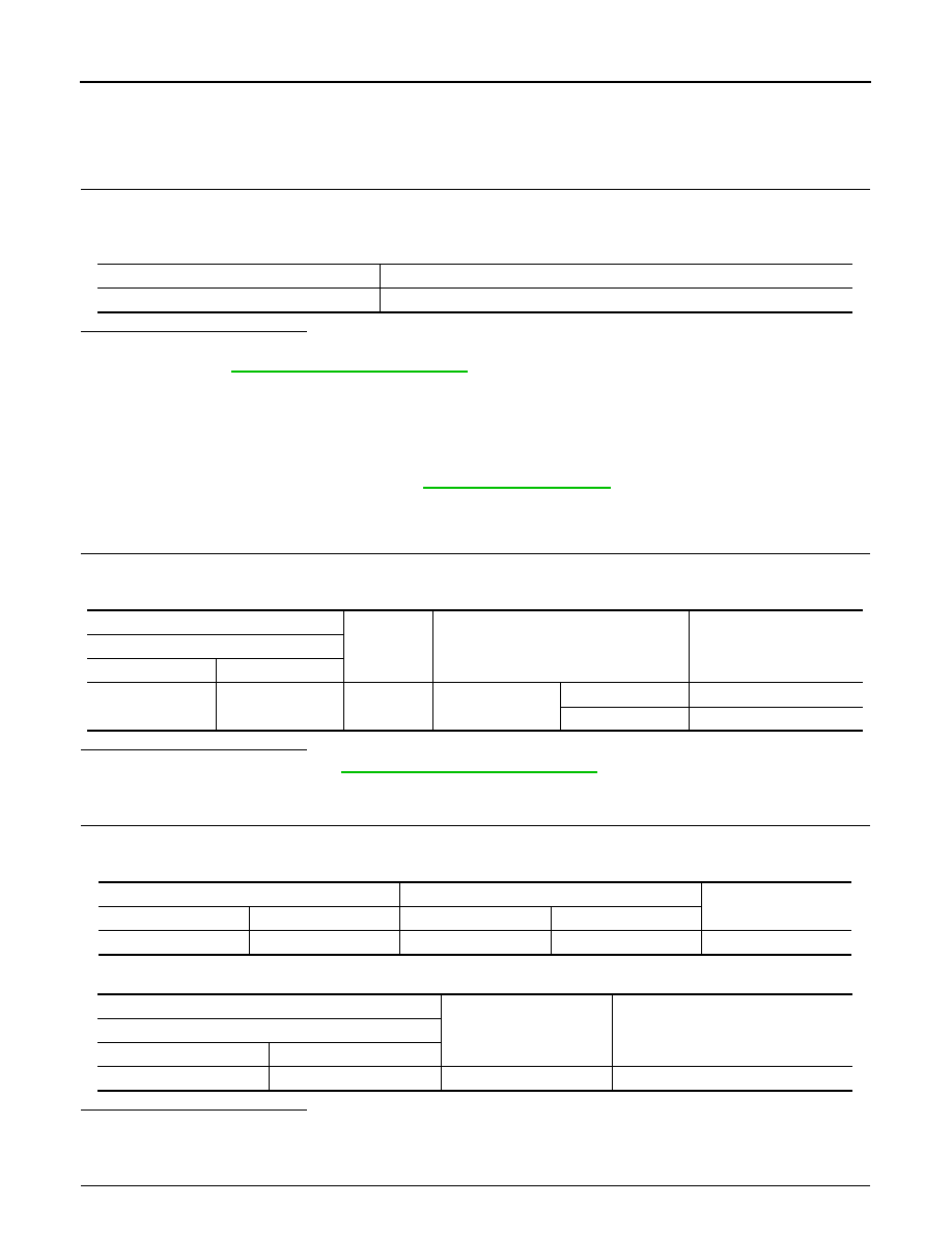
2. Check voltage between BCM harness connector and ground.

Is the inspection result normal?

YES

>> Replace BCM. Refer to 

BCS-73, "Removal and Installation"

.

NO

>> GO TO 2.

2.

CHECK REMOTE KEYLESS ENTRY RECEIVER CIRCUIT 1

1. Disconnect BCM and remote keyless entry receiver connectors.

2. Check continuity between BCM harness connector and remote keyless entry receiver harness connector.

3. Check continuity between BCM harness connector and ground.

Is the inspection result normal?

YES

>> GO TO 3.

NO

>> Repair or replace harness.

3.

CHECK REMOTE KEYLESS ENTRY RECEIVER POWER SUPPLY 

Monitor item

Condition

RKE OPE COUN1

Checks whether value changes when operating Intelligent Key

(+)

(–)

Condition

Signal

(Reference value)

BCM

Connector

Terminal

M84

38

Ground

Push-button igni-
tion switch

OFF or ACC

0 - 0.5V

ON

Battery voltage

BCM

Remote keyless entry receiver

Continuity 

Connector

Terminal

Connector

Terminal

M84

38

M91

2

Yes

(+)

(–)

Continuity

BCM

Connector

Terminal

M84

38

Ground

No

REMOTE KEYLESS ENTRY RECEIVER

DLK-109

< DTC/CIRCUIT DIAGNOSIS >

[WITH INTELLIGENT KEY SYSTEM]

C

D

E

F

G

H

I

J

L

M

A

B

DLK

N

O

P

Check voltage between remote keyless entry receiver harness connector and ground.

Is the inspection result normal?

YES

>> GO TO 4.

NO-1 >> Check 10A fuse No. 14 [located in fuse block J/B].

NO-2 >> Repair or replace harness between BCM and 10A fuse No. 14.

4.

CHECK REMOTE KEYLESS ENTRY RECEIVER GROUND CIRCUIT 

Check continuity between remote keyless entry receiver harness connector and ground.

Is the inspection result normal?

YES

>> Replace remote keyless entry receiver. Refer to 

DLK-199, "Removal and Installation"

.

NO

>> Repair or replace harness.

(+)

(–)

Voltage

Approx.

Remote keyless entry receiver

Connector

Terminal

M91

1

Ground

Battery voltage

Remote keyless entry receiver

Ground

Continuity

Connector

Terminal

M91

4

Yes

DLK-110

< DTC/CIRCUIT DIAGNOSIS >

[WITH INTELLIGENT KEY SYSTEM]

SHIFT P WARNING LAMP

SHIFT P WARNING LAMP

Component Function Check

INFOID:0000000009756414

1.

CHECK FUNCTION

1. Select INTELLIGENT KEY of BCM using CONSULT.

2. Select LCD in ACTIVE TEST mode.

3. Touch SET P to check that it works normally.
Is the inspection result normal?

YES

>> Shift P warning lamp is OK.

NO

>> Refer to 

DLK-110, "Diagnosis Procedure"

.

Diagnosis Procedure

INFOID:0000000009756415

1.

CHECK SHIFT P WARNING LAMP

Refer to 

DLK-31, "WARNING FUNCTION : System Description"

.

Is the inspection result normal?

YES

>> GO TO 2.

NO

>> Repair or replace the malfunctioning parts.

2.

CHECK INTERMITTENT INCIDENT

Refer to 

GI-39, "Intermittent Incident"

.

>> Inspection End.

TRUNK LID OPENER ACTUATOR

DLK-111

< DTC/CIRCUIT DIAGNOSIS >

[WITH INTELLIGENT KEY SYSTEM]

C

D

E

F

G

H

I

J

L

M

A

B

DLK

N

O

P

TRUNK LID OPENER ACTUATOR

Component Function Check

INFOID:0000000009756416

1.

CHECK FUNCTION

1. Select INTELLIGENT KEY of BCM using CONSULT.

2. Select TRUNK/GLASS HATCH in ACTIVE TEST mode.

3. Touch OPEN to check that it works normally.
Is the inspection result normal?

YES

>> Trunk lid opener actuator is OK.

NO

>> Refer to 

DLK-111, "Diagnosis Procedure"

.

Diagnosis Procedure

INFOID:0000000009756417

Regarding Wiring Diagram information, refer to 

DLK-63, "Wiring Diagram"

.

1.

CHECK TRUNK LID OPENER INPUT SIGNAL

1. Turn ignition switch OFF.

2. Disconnect trunk lid opener assembly connector.

3. Check voltage between trunk lid opener assembly harness connector and ground.

Is the inspection result normal?

YES

>> GO TO 3.

NO

>> GO TO 2.

2.

CHECK TRUNK LID OPENER ACTUATOR CIRCUIT

1. Disconnect BCM connector.

2. Check continuity between BCM harness connector and trunk lid opener assembly harness connector. 

3. Check continuity between BCM harness connector and ground.

Is the inspection result normal?

YES

>> Replace BCM. Refer to 

BCS-73, "Removal and Installation"

.

NO

>> Repair or replace harness.

3.

CHECK TRUNK LID OPENER ACTUATOR GROUND CIRCUIT

Check continuity between trunk lid opener assembly harness connector and ground.

(+)

(–)

Condition

Voltage

(Approx.)

Trunk lid opener assembly

Connector

Terminal

B59

3

Ground

Trunk lid opener switch is ON

12 V

BCM

Trunk lid opener assembly

Continuity 

Connector

Terminal

Connector

Terminal

B24

107

B59

3

Yes

BCM

Ground

Continuity 

Connector

Terminal

B24

107

No


Content   ..  246  247  248  249   ..