Nissan Sentra. Manual - part 217


  Index      Nissan     Nissan Sentra (2014 year) - Service and Repair Manual


Search            


Content   ..  215  216  217  218   ..


Nissan Sentra. Manual - part 217


REAR WINDOW DEFOGGER POWER SUPPLY AND GROUND CIRCUIT

DEF-33

< DTC/CIRCUIT DIAGNOSIS >

C

D

E

F

G

H

I

J

K

M

A

B

DEF

N

O

P

REAR WINDOW DEFOGGER POWER SUPPLY AND GROUND CIRCUIT

Description

INFOID:0000000009759103

Heats the heating wire with the power supply from the rear window defogger relay to prevent the rear window

from fogging up.

Component Function Check

INFOID:0000000009759104

1.

 CHECK REAR WINDOW DEFOGGER

Check that the heating wire of rear window defogger is heated when turning the rear window defogger switch

ON.
Is the inspection result normal?

YES

>> Rear window defogger is OK.

NO

>> Refer to 

DEF-33, "Diagnosis Procedure"

.

Diagnosis Procedure

INFOID:0000000009759105

Regarding Wiring Diagram information, refer to 

DEF-20, "Wiring Diagram"

.

1.

 CHECK FUSES 

Check if any of the following fuses in IPDM E/R are blown.

Is the inspection result normal?

YES

>> GO TO 2.

NO

>> Replace the blown fuse after repairing the affected circuit.

2.

 CHECK REAR WINDOW DEFOGGER POWER SUPPLY CIRCUIT

1. Turn ignition switch ON.

2. Check voltage between IPDM E/R connector and ground.

Is the inspection result normal?

YES

>> GO TO 3.

NO

>> Perform rear window defogger relay diagnosis. Refer to 

DEF-32, "Diagnosis Procedure"

.

3.

 CHECK POWER SUPPLY CIRCUIT

1. Turn ignition switch ON.

2. Check voltage between rear window defogger connector and ground.
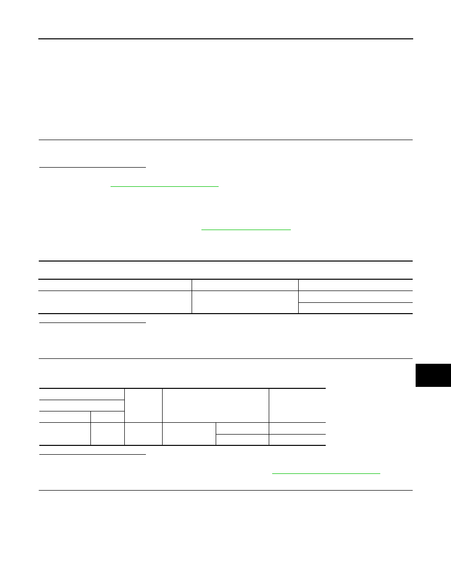
COMPONENT PARTS

AMPERE

FUSE NO.

IPDM E/R

15A

31

32

(+)

(–)

Condition

Voltage (V)

(Approx.)

IPDM E/R

 Connector

Terminal 

E48

62

Ground

Rear window de-

fogger switch 

ON Battery 

voltage

OFF 0

DEF-34

< DTC/CIRCUIT DIAGNOSIS >

REAR WINDOW DEFOGGER POWER SUPPLY AND GROUND CIRCUIT

Is the inspection result normal?

YES

>> GO TO 4.

NO

>> GO TO 5.

4.

 CHECK GROUND CIRCUIT

1. Turn ignition switch OFF.

2. Disconnect rear window defogger.

3. Check continuity between rear window defogger connector and ground.

Is the inspection result normal?

YES

>> GO TO 6.

NO

>> Repair or replace harness.

5.

 CHECK HARNESS CONTINUITY

1. Turn ignition switch OFF.

2. Disconnect IPDM E/R.

3. Check continuity between IPDM E/R connector and condenser connector.

Is the inspection result normal?

YES

>> Replace condenser. Refer to 

DEF-49, "Removal and Installation"

.

NO

>> Replace or repair harness.

6.

 CHECK FILAMENT

Check filament.

Refer to 

DEF-34, "Component Inspection"

.

Is the inspection result normal?

YES

>> Refer to 

GI-39, "Intermittent Incident"

.

NO

>> Repair filament. Refer to 

DEF-47, "Inspection and Repair"

.

Component Inspection

INFOID:0000000009759106

1.

 CHECK FILAMENT

Check the filament for damage or open circuits.

Refer to 

DEF-47, "Inspection and Repair"

.

Is the inspection result normal?

YES

>> Inspection End.

NO

>> Repair filament. Refer to 

DEF-47, "Inspection and Repair"

.

(+)

(–)

Condition

Voltage (V)

(Approx.)

Rear window defogger

 Connector

Terminal 

B62

1

Ground

Rear window de-

fogger switch 

ON Battery 

voltage

OFF 0

Rear window defogger

Ground

Continuity

Connector

Terminal

B63

2

Yes

IPDM E/R

Condenser

Continuity 

Connector

Terminal

Connector

Terminal

E48 62

B50

1

Yes

DRIVER SIDE DOOR MIRROR DEFOGGER

DEF-35

< DTC/CIRCUIT DIAGNOSIS >

C

D

E

F

G

H

I

J

K

M

A

B

DEF

N

O

P

DRIVER SIDE DOOR MIRROR DEFOGGER

Description

INFOID:0000000009759107

Heats the heating wire with the power supply from the rear window defogger relay to prevent the door mirror

from fogging up.

Component Function Check

INFOID:0000000009759108

1.

 CHECK DOOR MIRROR DEFOGGER LH

Check that heating wire of door mirror defogger LH is heated when turning the rear window defogger switch

ON.
Is the inspection result normal?

YES

>> Door mirror defogger is OK.

NO

>> Refer to 

DEF-35, "Diagnosis Procedure"

.

Diagnosis Procedure

INFOID:0000000009759109

Regarding Wiring Diagram information, refer to 

DEF-20, "Wiring Diagram"

.

1.

 CHECK POWER SUPPLY CIRCUIT 

1. Turn ignition switch OFF.

2. Disconnect door mirror LH. 

3. Turn ignition switch ON.

4. Check voltage between door mirror LH connector and ground.

Is the inspection result normal?

YES

>> GO TO 2.

NO

>> Repair or replace harness.

2.

 CHECK GROUND CIRCUIT

1. Turn ignition switch OFF.

2. Check continuity between door mirror LH connector and ground.

Is the inspection result normal?

YES

>> GO TO 3.

NO

>> Repair or replace harness.

3.

 CHECK DOOR MIRROR DEFOGGER LH

Check door mirror defogger LH.

Refer to 

DEF-36, "Component Inspection"

.

Is the inspection result normal?

YES

>> GO TO 4.

NO

>> Replace door mirror. Refer to 

MIR-18, "DOOR MIRROR ASSEMBLY : Removal and Installation"

.

(+)

(–)

Condition

Voltage (V)

(Approx.)

Door mirror LH

 Connector

Terminal 

D7

3

Ground

Rear window de-

fogger switch 

ON Battery 

voltage

OFF 0

Door mirror LH

Ground

Continuity

Connector

Terminal

D7

9

Yes

DEF-36

< DTC/CIRCUIT DIAGNOSIS >

DRIVER SIDE DOOR MIRROR DEFOGGER

4.

 CHECK INTERMITTENT INCIDENT

Check intermittent incident.

Refer to 

GI-39, "Intermittent Incident"

.

Is the inspection result normal?

YES

>> Check the following.

• Battery power supply circuit.

• Fuse block (J/B).

NO

>> Repair or replace the malfunctioning parts.

Component Inspection

INFOID:0000000009759110

1.

 CHECK DOOR MIRROR DEFOGGER LH

1. Turn ignition switch OFF.

2. Disconnect door mirror LH.

3. Check continuity between door mirror terminals.

Is the inspection result normal?

YES

>> Inspection End.

NO

>> Replace door mirror LH. Refer to 

MIR-18, "DOOR MIRROR ASSEMBLY : Removal and Installa-

tion"

.

Terminal Continuity 

3

9

Yes


Content   ..  215  216  217  218   ..